Introduction and Concepts
In this guide, we will go over some of the bigger concepts that underlie the Material Editor. Many of these ideas are common to real-time computer graphics, so you may be familiar with a few of them already. If not, don’t worry, we’re here to help!
What Are Materials?
Materials are assets that describe where to draw a 2d or 3d object, and what that object looks like.
A material is composed of small programs called shaders. Shaders run on the GPU (the graphics chip on your phone), which makes them very fast.
The Material Editor lets you easily create two shaders that define your material: the vertex shader and the pixel shader.
While it may seem odd that we are talking about making computer programs yet we are not writing any code, that is indeed the power of Material Editor!
Vertex Shader
The vertex shader is a small program that runs on every vertex of your object. It is primarily used to move, or transform, vertices.
Vertex shaders are always processed first.
Pixel Shader
The pixel shader, also known as a fragment shader, is a small program that runs on every pixel of the screen that your object occupies. You can use the pixel shader to change the color and opacity of your object.
Pixel shaders are always processed second, after the Vertex shader.
In the world of shaders, colors are simply numbers that can be added, multiplied, and combined with other values using normal math operations. You can even simulate lighting in the pixel shader, which is what our PBR node does for you.
Node Graph
The Material Editor uses a node graph to represent the materials you create. Nodes stand in for blocks of code that you can connect together to create a shader. Together, the vertex and pixel shaders form a material.
Creating a Material

Materials are defined by what you connect to the Shader node.
Nodes that contribute to the blue inputs - World Position (Vertex), World Normal (Vertex), and World Tangent (Vertex) - are written into the vertex shader.
Nodes that contribute to the purple input - Color (Pixel) - are written into the pixel shader.
Data Flow
The node graph flows from left to right, always ending at the Shader node. A node’s inputs are on the left side and its outputs are on the right side. Outputs can not be connected to inputs (otherwise that would cause a feedback loop).
The Vertex shader is processed first, followed by the Pixel shader.
Sub-Graphs
Groups of nodes can be collected into a single node called a sub-graph. Sub-graphs have special Import and Export nodes that let you define the inputs and outputs of the sub-graph.
Sub-graphs are useful for organizing your node network and reusing common operations. Since sub-graphs can be exported as files, you can create your own library of sub-graphs that you can drop in other materials, or share them with the community.
We have included several useful sub-graphs in Material Library that show up in the node list. Feel free to dive into our sub-graphs and see how we built them!
Surface Nodes

Surface nodes gives you access to various attributes relating to the geometry your material is assigned to. These attributes are data that are attached to your model when you add it to Lens Studio and include things such as the position, the normals, and the UVs.
If you write an attribute to the Vertex Shader, such as the World Position (Vertex), the corresponding Surface (Position) node will use that new value in the Pixel shader.
Interpolators
When Surface nodes are used in a Pixel shader, their values are automatically interpolated from vertices to pixels. You can think of interpolation as blending between the closest vertices.
If you create data in a vertex shader that you want to use on a pixel shader, you can pass that data through an Interpolator node to explicitly interpolate it from vertices to pixels.
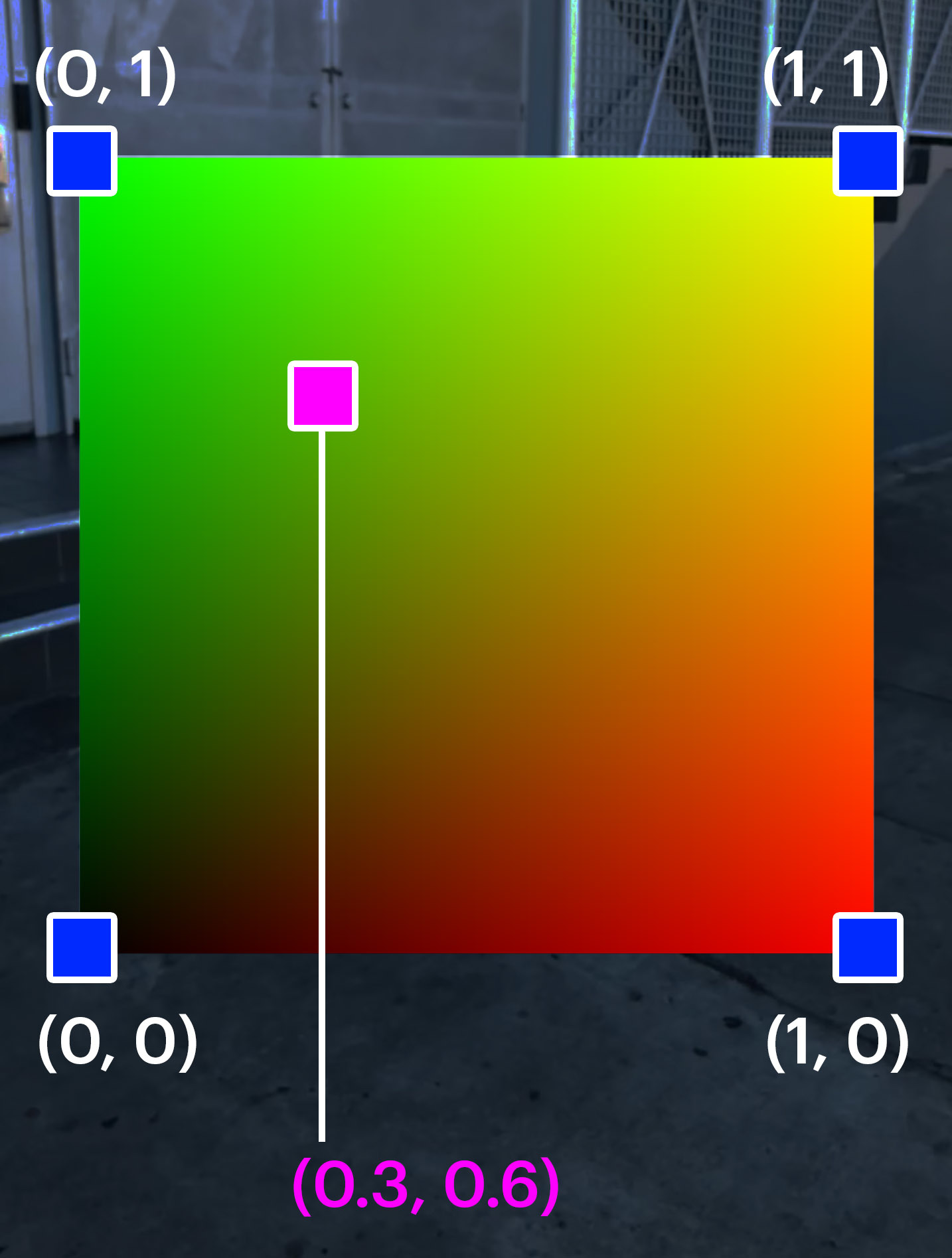
In the image above, the blue squares in the corners are UV positions in x and y. This would be the data you would get when using Surface UV Coord in a vertex shader, where only individual vertices exist. If you use Surface UV Coord in a pixel shader however, the value is a blend between the nearest vertices, as represented by the magenta square.
The plane in this image was rendered using the Surface UV Coord as the color. Notice how the colors smoothly change across the plane.