Cubemap
This guide will show you how the Cubemap Template can be used and offers several examples of how to create and use cubemaps in Lens Studio.
It is recommended that you have an understanding of how Cubemaps function. Please see the Cubemap Guide to learn more about how Cubemaps are used in Lens Studio.
This template works best using the Interactive preview.
Cubemap Import
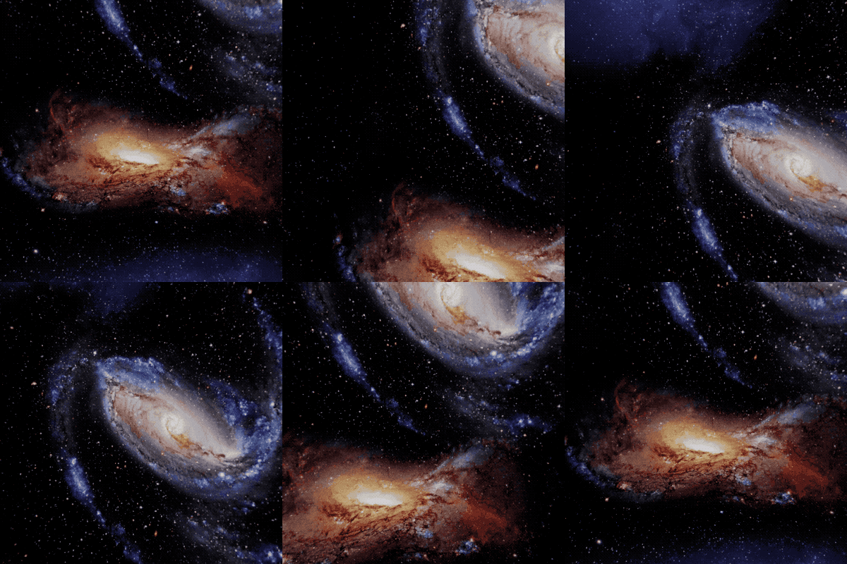
The first thing you’ll see when you open the project is an example of importing cubemaps from a file to create a space-themed environment dome. This is the simplest and easiest to implement use case for cubemaps.
You can look around the environment dome by using the Interactive Preview or by using Send to Snapchat to try the lens on your device.
How It Works
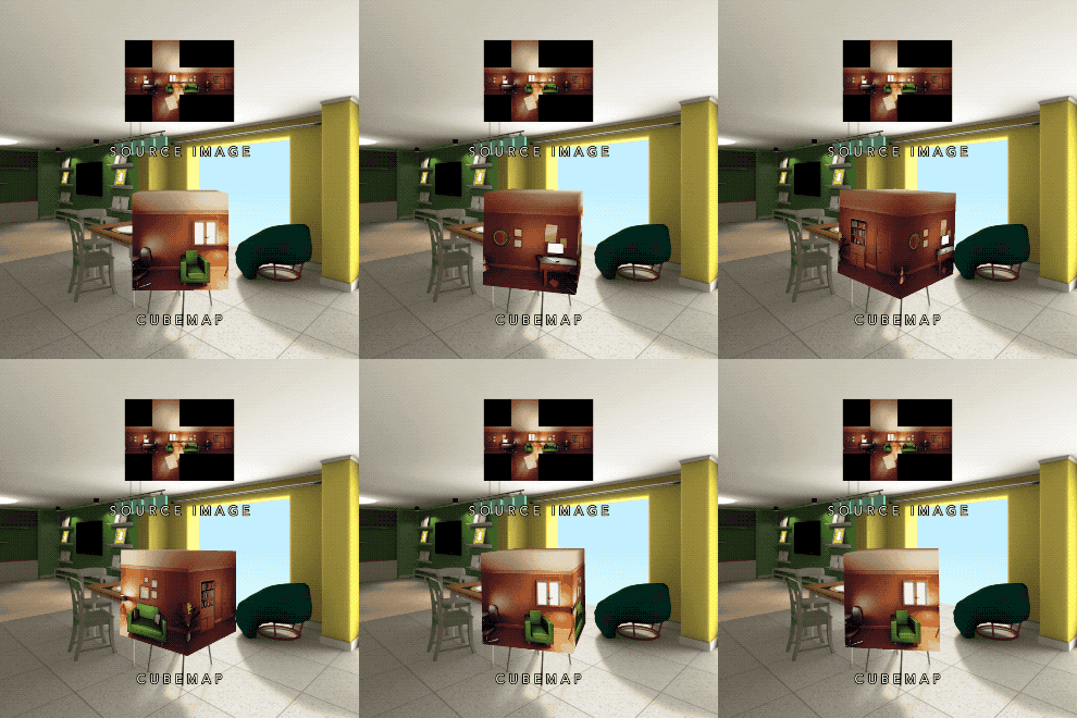
To show how the cubemap works, the Room view example shows a simple cubemap used to create a room. The Debug view example has labels showing where the positive and negative x, y, and z faces are.
In both examples, the top rectangle shows the raw cubemap image file when imported as a regular texture. In this case, the source image is shown in horizontal cross format, but vertical cross is also supported.
After going through the cubemap import process, the image file becomes a cubemap that you can use as a sample in a material. The box materials for both the Room and Debug examples are sampling their respective cubemaps, which are pictured in their corresponding source images.
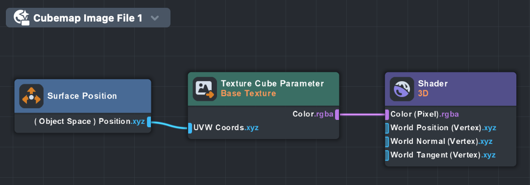
The materials on the boxes are very simple: a Texture Cube Parameter both creates a cubemap texture parameter and samples it with the given UVW Coords. This gives it the mesh’s object space positions as sampling coordinates.
Cubemap Rendering
Rendering into a cubemap is a little more involved than importing cubemaps from image files, so these examples provide an easy entry-point for working with this powerful feature. The three sections; Introduction, Reflection, and Disco Ball World Mesh—each build off one another and increase in complexity.
All of the cubemap rendering examples use the Cubemap Camera custom component. For more information on this custom component and a detailed look at how cubemap rendering works, please see Rendering Cubemaps in Lens Studio in the Cubemap Guide.
Introduction
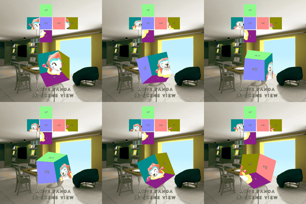
This introductory example shows how to render a layer set into a cubemap render target, then sample it on a variety of materials.
Cubemap sampling is also available in VFX.
The first thing to understand about this example is that the dancing panda, the different colors, and the axis labels are all being rendered offscreen in a separate layer.
The screenshot below shows the scene we are rendering into the cubemap render target:
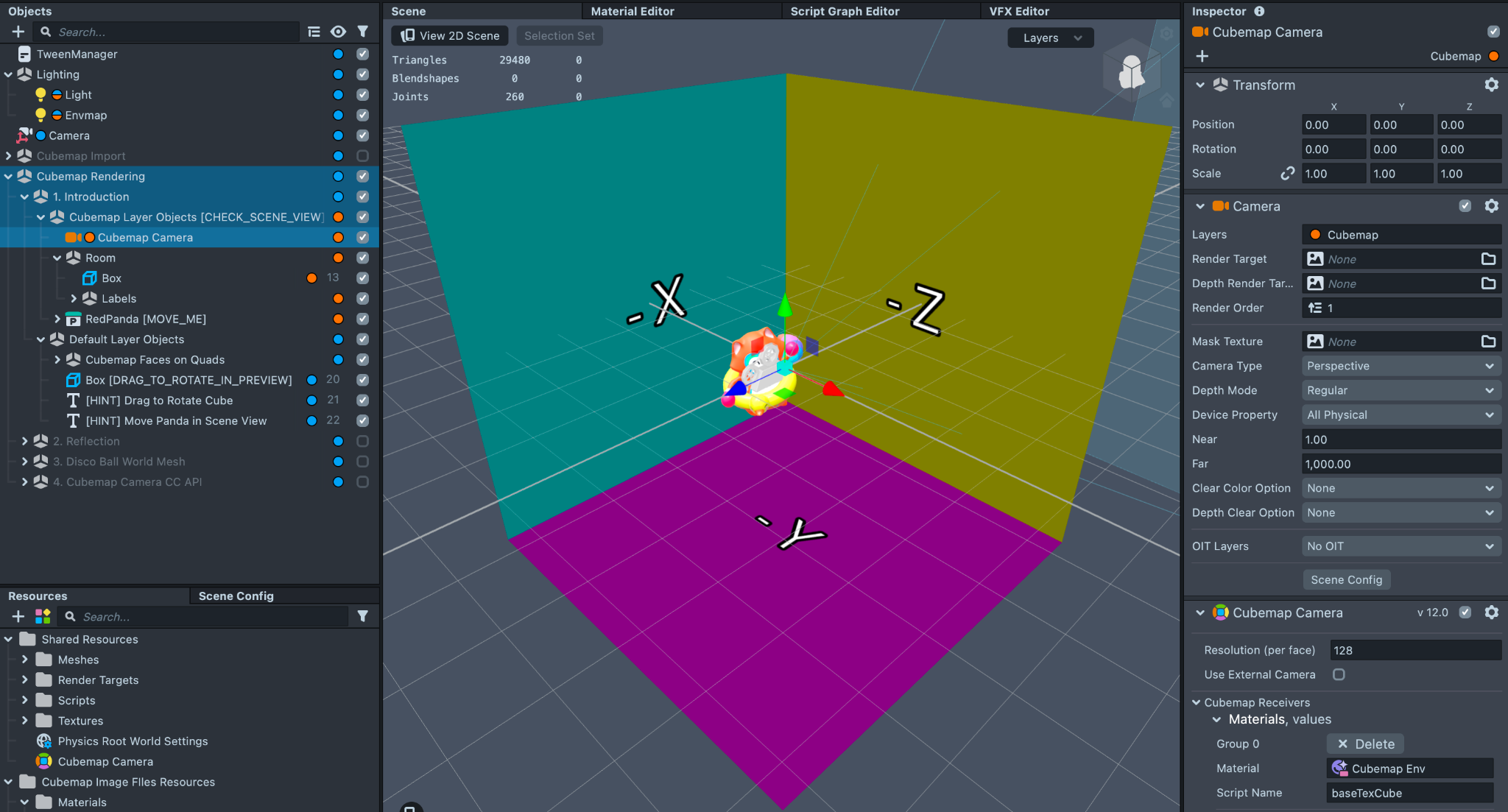
The Cubemap Camera object has its Layers property set to Cubemap (instead of Default), and it has a Cubemap Camera custom component attached to it with all the materials and mesh visuals assigned that need to receive the cubemap render target. The scene is organized such that everything assigned to the Cubemap layer is under the Cubemap Layer Objects group, and everything that’s rendered to the screen in the Default layer is under the Default Layer Objects group.
The box material is identical to the Cubemap Image File material described in the first section of this guide. The Cubemap Faces are a little different: they have a Code Node that creates an axis-aligned orthographic vector for sampling a given face of the cubemap. This can be very useful for debugging.

Reflection
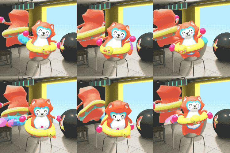
The reflection example shows how cubemap rendering can be used to create reflections in real time.
In the scene, we have two copies of the dancing panda: one is rendered to the screen in the Default layer, and one is rendered into a cubemap render target and assigned to the Cubemap layer.
Each object that needs a reflection also needs its own cubemap render target, so the reflecting sphere and box each have a Cubemap Camera as a sibling that moves around with them. These cameras have Cubemap Camera Custom Components which send the cubemap render target to their respective materials. The cubemap cameras are effectively reflection probes since they are each capturing a spherical view of their surroundings.

In this example, the only thing being reflected is the dancing panda, but it’s easy to add any other objects you want to the Cubemap layer to include them in the reflection.
Note that each instance of the Cubemap Camera Helper produces its own cubemap render target, each with their own independent resolution settings. It’s best to try and keep that number as small as possible so the lens performs well on all devices.
In this example, the sphere has a resolution of 128. You can get away with a lower resolution on the sphere since it’s smaller on the screen and the artifacts are less noticeable. However, The box’s cubemap uses the max resolution of 2048. While this helps prevent aliasing on flat surfaces, it has a significantly higher performance cost.
Try changing the box’s resolution to other values, such as 512 and 1024, to see how resolution affects visuals and performance.
Disco Ball World Mesh
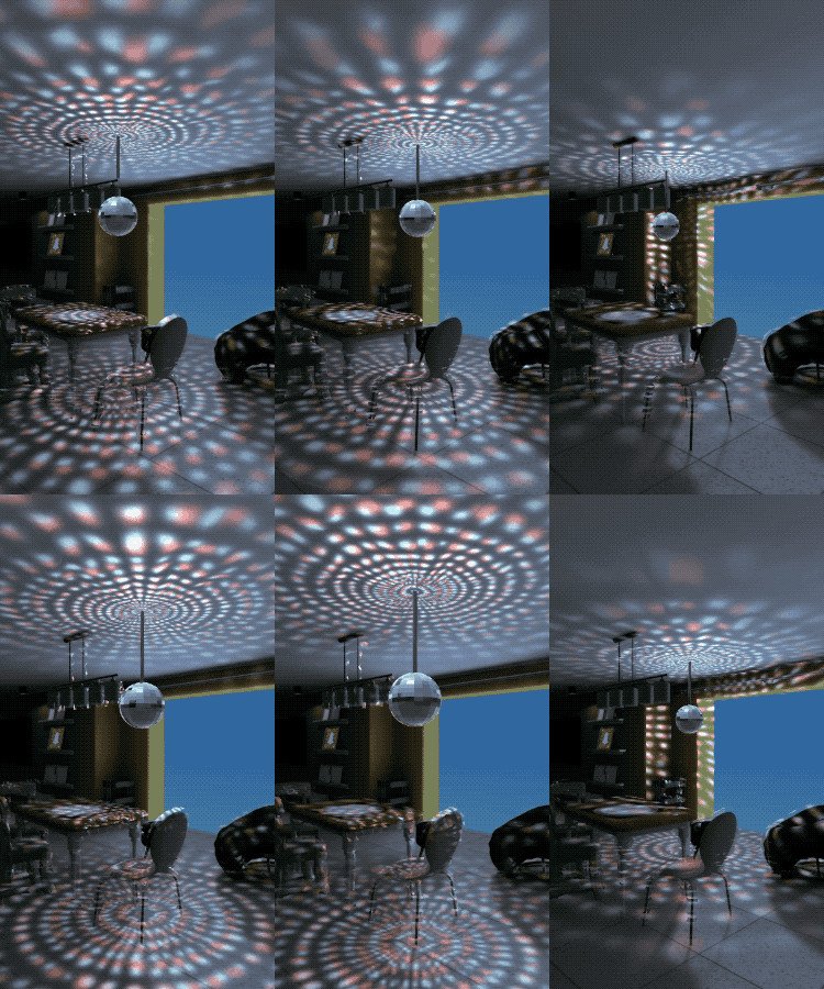
This example applies a disco ball-like lighting effect to the world mesh.
The setup here is similar to the other cubemap rendering examples, except in this one we do a little extra work in the world mesh material to map the discoball’s location to the cubemap sample vector.
First, a cubemap render target is created which captures a sphere with a custom material called Discoball Env. The job of this material is to produce the lighting effect you want to project onto the world. The material samples a black and white texture that looks like a grid of little rectangles and offsets and colors them. When applied to a sphere, the result looks like this:
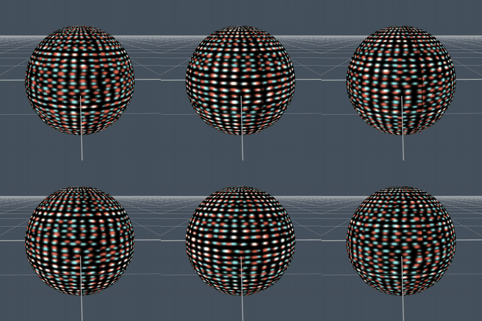
With a cubemap camera placed inside the sphere, the resulting cubemap render target becomes like a skydome with the lighting effect on it. The only thing to do now is to sample the cubemap correctly so it looks like it’s attached to the disco ball in the scene.
The cubemap is sampled in the World Mesh Cubemap Lighting material via a Code Node titled Cubemap Lighting. You can see where this happens on line 27 in the Code Node:
vec3 samplePointCubemap = (TargetMatInv * vec4(system.getSurfacePosition(), 1.0)).xyz;
vec4 cubemapSample = CubemapTex.sample(samplePointCubemap);
Here, the template transform the world mesh’s world space surface position into the space of the disco ball scene object. The disco ball scene object is represented by the TargetMatInv variable, which is simply the disco ball scene object’s inverse transform matrix. The material receives this matrix from a script, Pass Transform to Material.js.
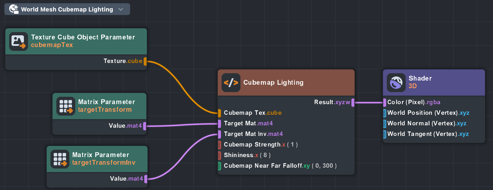
The rest of the Code Node is responsible for computing diffuse and specular scaling factors, as well as distance falloff based on the disco ball scene object’s location. Finally, the resulting cubemap lighting value is sent to the Color port on the Shader 3D Node. You can then apply this visual effect to the scene by setting this material’s Blend Mode to Add.
Cubemap Camera CC API
At first glance, this looks similar to the Introduction example for Cubemap Rendering, but at a much lower resolution. The difference is that instead of using a Cubemap Camera custom component explicitly, the cubemap camera is created by another script using the custom component’s API.
This allows for more dynamic control over cubemap cameras for complex lenses that require complex logic and behavior.