Procedural Mesh
Overview
With the help of the Mesh Builder class, Lens Studio supports you to dynamically manipulate 3D mesh on the vertex-level in run-time. This will enable you to achieve procedural effects. Using MeshBuilder, you can dynamically add or delete vertices, and move each vertex as you like.
Getting Started
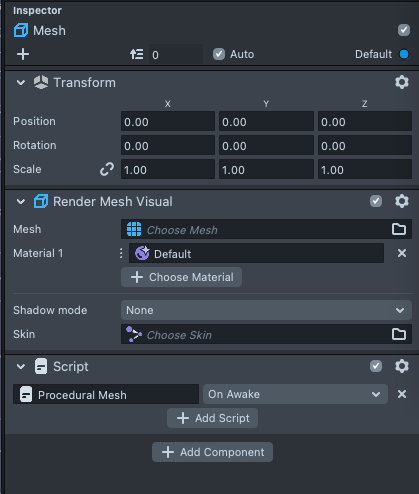
Open a new Lens Studio project. Add a new Mesh Object in the Scene Hierarchy panel by pressing the + button and selecting the empty Mesh.

In the Asset Browser panel, select + → Script. With our object selected, add a Script component in the Inspector panel. Select + Add Component → Script. Then select the + Add Script field and select the script resource we just created.
Open up the script and we can initiate a new procedural mesh with the Mesh Builder class.
//@input Component.MeshVisual meshVisual
var builder = new MeshBuilder([{ name: 'position', components: 3 }]);
builder.topology = MeshTopology.Points;
This code will create an empty procedural mesh. The constructor defines what property that we can manipulate. In this case, we can manipulate the position of each vertex that forms the procedural mesh. After the constructor, we define the topology type of our procedural mesh object to be points.
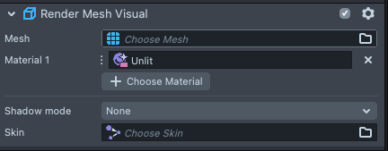
Last step is to assign a material to the mesh, so that we can control the color of our mesh in the Lens Studio editor or use code to dynamically control the color of the mesh. In the Asset Browser panel, select + → Unlit Material. We can then attach the unlit material to the Render Mesh Visual Component.
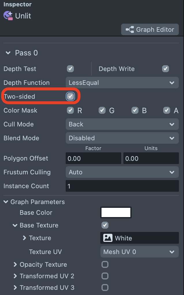
Double click on the Unlit Material. In the Material Editor connect the surface color node to the base color in the graph editor.
We can also enable two-sided in the material so that the mesh can be seen from both sides:
Indices
A 3D mesh is formed by a group of vertices. In MeshBuilder, each vertex is assigned with a unique index number based on the order of vertex being added to the MeshBuilder object.
In MeshBuilder, there are two levels of data:
The first level stores information for each vertex, such as the vertex’s position, color, normal, and etc. The information is stored under corresponding vertices.
What is stored per vertex is defined by the Builder. For example, if you wanted to store both position and color as in the image above, in your builder you would write:
var builder = new MeshBuilder([
  { name: 'position', components: 3 },
  { name: 'color', components: 4 },
]);
The second level stores an array of vertex’s indices. Rather than from vertex 0 to vertex 2 like in the first level, we can have them stored in a customized order with repetition and the MeshBuilder will group vertices based on the order. Under different topology types, the grouping will be different.
For example under Triangle Topology, the Mesh Builder will group every three vertices to render a triangle based on the information stored under each vertex. With the code below, a triangle can be formed by vertex 0, 1, 2. The second triangle can be built with the reversed order of indices. This code will give us two triangles facing opposition directions:
builder.appendIndices([
   0, 1, 2 // Triangle 1
   2, 1, 0 // Triangle 2
]);
Topology
At the initiating state of a Mesh Builder object, topology defines how we apply the function: appendIndices(). Here are the explanations and examples for each topology type.
Points
By selecting points, the procedural mesh will only render points (vertex) on the screen without any line or face. We can add the 3D position for each point that we want to add with appendVerticesInterleaved().
builder.appendVerticesInterleaved([
  // Position             Index
  0,
  0,
  0, // 0
]);
The code adds three points to our procedural mesh as data. The points are at [0,0,0]. As the topology is points, the mesh is rendered as points. We can use appendIndices() to add the index of the vertices that we want to render.
builder.appendIndices([0]);
After we assign procedural mesh to a scene object and update the mesh with the following code, we will have our first point procedurally generated at position [0,0,0]:
script.meshVisual.mesh = builder.getMesh();
builder.updateMesh();
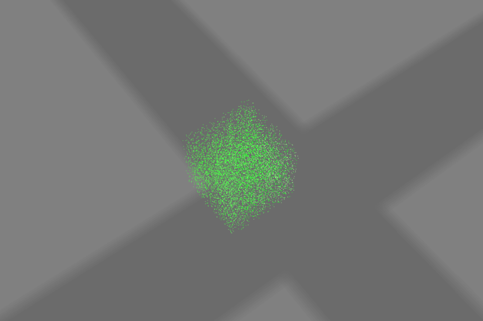
Please note that one point takes a single pixel to render, this may make it challenging to see on the screen. However, we can loop this code 10000 times to see a cluster of points. The complete code:
//@input Component.MeshVisual meshVisual
var builder = new MeshBuilder([
  { name: 'position', components: 3 }, //attribute 1
]);

builder.topology = MeshTopology.Points;
for (var i = 0; i < 10000; i++) {
  builder.appendVerticesInterleaved([
    // Position
    Math.random(),
    Math.random(),
    Math.random(),
  ]);

  builder.appendIndices([i]);
}
script.meshVisual.mesh = builder.getMesh();
builder.updateMesh();
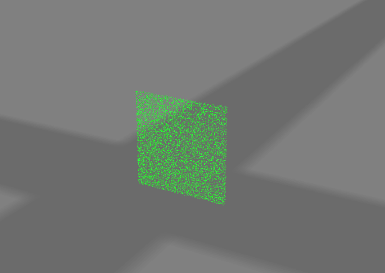
By control the position of the points that we want to add, we can also have a square face:
//@input Component.MeshVisual meshVisual

var builder = new MeshBuilder([
  { name: 'position', components: 3 }, //attribute 1
]);

builder.topology = MeshTopology.Points;
for (var i = 0; i < 10000; i++) {
  builder.appendVerticesInterleaved([
    // Position
    Math.random(),
    i / 10000,
    0,
  ]);

  builder.appendIndices([i]);
}
script.meshVisual.mesh = builder.getMesh();
builder.updateMesh();
Or a line with the code:
//@input Component.MeshVisual meshVisual

var builder = new MeshBuilder([
  { name: 'position', components: 3 }, //attribute 1
]);

builder.topology = MeshTopology.Points;
for (var i = 0; i < 10000; i++) {
  builder.appendVerticesInterleaved([
    // Position
    0,
    i / 10000,
    0,
  ]);

  builder.appendIndices([i]);
}
script.meshVisual.mesh = builder.getMesh();
builder.updateMesh();
This method to make a line or face is both inconvenient and inefficient. Here are a few topologies that can enable you to quickly build lines and faces.
Lines
Lines can be defined by the two points at both ends, so with the Lines topology, our MeshBuilder will render a line between every two vertices. We first need to change the topology from Points to Lines:
builder.topology = MeshTopology.Lines;
In this mode, indices are lines, each formed by two vertices. We first need to add two vertices and a third vertex for later demo:
builder.appendVerticesInterleaved([
  // Position      Index
  0,
  0,
  0, //0
  0,
  10,
  0, //1
  10,
  0,
  0, //2
]);
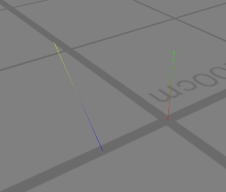
Then we append the index of vertices to our mesh builder so it renders a line between vertex 0 and vertex 1.
builder.appendIndices([
  0,
  1, // Line 1
]);
Here is the rendered result:

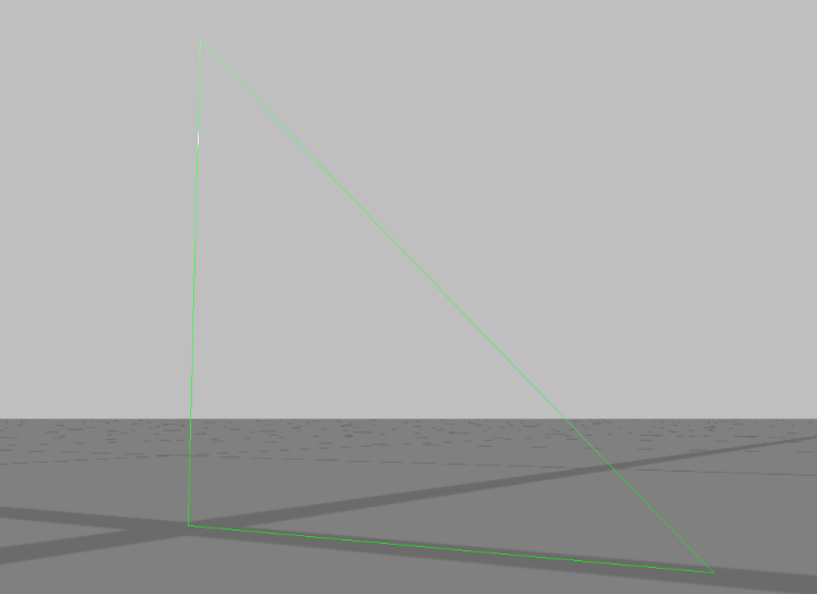
We can also connect all three vertices by changing the code in appendIndices(). Notice that we can reuse the used vertices to form this triangle:
//@input Component.MeshVisual meshVisual

var builder = new MeshBuilder([
  { name: 'position', components: 3 }, //attribute 1
]);

builder.topology = MeshTopology.Lines;
builder.indexType = MeshIndexType.UInt16;

builder.appendVerticesInterleaved([
  // Position      Index
  0,
  0,
  0, //0
  0,
  10,
  0, //1
  10,
  0,
  0, //2
]);

builder.appendIndices([
  0,
  1, // Line 1
  1,
  2, // Line 2
  2,
  0, // Line 3
]);

script.meshVisual.mesh = builder.getMesh();
builder.updateMesh();
By adding color property in the constructor, we can also get these colored lines not connected together in our procedural mesh with the code below:
The complete code for this example:
//@input Component.MeshVisual meshVisual

var builder = new MeshBuilder([
  { name: 'position', components: 3 }, //attribute 1
  { name: 'color', components: 4 }, //attribute 2
]);

builder.topology = MeshTopology.Lines;
builder.indexType = MeshIndexType.UInt16;

builder.appendVerticesInterleaved([
  // Position             Color                   Index
  0,
  0,
  0,
  1,
  0,
  0,
  1, // 0
  0,
  10,
  0,
  0,
  1,
  0,
  1, // 1
  10,
  0,
  0,
  0,
  0,
  1,
  1, // 2
  10,
  10,
  10,
  1,
  1,
  0,
  1, // 3
]);
builder.appendIndices([
  0,
  1, // Line 1
  2,
  3, // Line 2
]);

script.meshVisual.mesh = builder.getMesh();
builder.updateMesh();
LineStrip
In some special cases when we want continuous lines head to tail, like in the graph below, we can use LineStrip with less code.

Unlike the Lines topology, which needs two vertices to render each line, LineStrip supports you to only use one new vertex to render a new line as it will automatically connect to the previous vertex appended. To make the same triangle in the previous example, we can do this:
//@input Component.MeshVisual meshVisual

var builder = new MeshBuilder([
  { name: 'position', components: 3 }, //attribute 1
]);

builder.topology = MeshTopology.LineStrip;
builder.indexType = MeshIndexType.UInt16;

builder.appendVerticesInterleaved([
  // Position      Index
  0,
  0,
  0, //0
  0,
  10,
  0, //1
  10,
  0,
  0, //2
]);

builder.appendIndices([
  0,
  1, // Line 1
  2, // Line 2
  0, // Line 3
]);

script.meshVisual.mesh = builder.getMesh();
builder.updateMesh();
Triangles
We can use Triangles Topology to make triangle faces. For each triangle, we need three vertices, and here is the code to make a basic triangle:
//@input Component.MeshVisual meshVisual

var builder = new MeshBuilder([{ name: 'position', components: 3 }]);

builder.topology = MeshTopology.Triangles;
builder.indexType = MeshIndexType.UInt16;

builder.appendVerticesInterleaved([
  // Position              Index
  0,
  0,
  0, // 0
  0,
  10,
  0, // 1
  10,
  0,
  0, // 2
]);

builder.appendIndices([
  0,
  1,
  2, // Our Triangle
]);

script.meshVisual.mesh = builder.getMesh();
builder.updateMesh();
Moreover, we can make a square with two triangles:
//@input Component.MeshVisual meshVisual

var builder = new MeshBuilder([{ name: 'position', components: 3 }]);

builder.topology = MeshTopology.Triangles;
builder.indexType = MeshIndexType.UInt16;

builder.appendVerticesInterleaved([
  // Position         Index
  0,
  0,
  0, // 0
  0,
  10,
  0, // 1
  10,
  0,
  0, // 2
  10,
  10,
  0, // 3
]);
builder.appendIndices([
  0,
  1,
  2, //Triangle 1
  1,
  2,
  3, //triangle 2
]);
script.meshVisual.mesh = builder.getMesh();
builder.updateMesh();

TriangleStrip
This mode is helpful if you want to create a strip like the graph below. In this case, each new vertex forms a new triangle with the previous two vertices.

Instead of defining each triangle with three vertices, we just need to add vertex indices in the right order and the MeshBuilder will automatically fill triangles like the graph.
To achieve the same shape as the previous example, we can append only 4 vertices in appendIndices():
//@input Component.MeshVisual meshVisual

var builder = new MeshBuilder([{ name: 'position', components: 3 }]);

builder.topology = MeshTopology.TriangleStrip;
builder.indexType = MeshIndexType.UInt16;

builder.appendVerticesInterleaved([
  // Position         Index
  0,
  0,
  0, // 0
  0,
  10,
  0, // 1
  10,
  0,
  0, // 2
  10,
  10,
  0, // 3
]);
builder.appendIndices([
  0,
  1, //First two vertices
  2, //triangle 1
  3, //triangle 2
]);

script.meshVisual.mesh = builder.getMesh();
builder.updateMesh();
TriangleFan
This mode is helpful if you want to create a fan shape like the graph below. In this case, each new vertex forms a new triangle with the previous vertex and the first vertex (vertex 0), instead of connecting the new vertex with the previous two vertices in TriangleStrip Topology.

In the previous example, we define the topology to be Triangles after the constructor. Thus, when we call appendIndices(), we need three vertices to define a set of indices to be a face. In the previous example, we have our triangle face defined by the first three vertices.
Skinned Meshes
Skinned Meshes are used to animate 3D models. The vertices of the mesh are attached to bones, and the bones are animated to move the vertices. The MeshBuilder class supports skinned meshes two ways:
1. VertexLayout
var simpleSkin = script.getSceneObject();
simpleSkin.createComponent('Component.Skin');
var mesh_0 = global.scene.createSceneObject('Mesh_0');
mesh_0.getTransform().setLocalScale(new vec3(100, 100, 100));
mesh_0.createComponent('Component.RenderMeshVisual');
mesh_0.setParent(simpleSkin);
var renderMeshVisual = mesh_0.getComponent('Component.RenderMeshVisual');
var skin = simpleSkin.getComponent('Component.Skin');

renderMeshVisual.setSkin(skin);

var armature = global.scene.createSceneObject('Armature');
armature.getTransform().setLocalScale(new vec3(100, 100, 100));
armature
  .getTransform()
  .setLocalRotation(quat.fromEulerVec(new vec3(-90, 0, 0)));
armature.setParent(simpleSkin);

var node_1 = global.scene.createSceneObject('Node_1');
node_1.getTransform().setLocalRotation(quat.fromEulerVec(new vec3(90, 0, 0)));
node_1.setParent(armature);

var Node_2 = global.scene.createSceneObject('Node_2');
Node_2.getTransform().setLocalPosition(new vec3(0.0, 1.0, 0.0));
Node_2.setParent(node_1);

var node_2_end = global.scene.createSceneObject('Node_2_end');
node_2_end.getTransform().setLocalPosition(new vec3(0.0, 1.0, 0.0));
node_2_end.setParent(Node_2);

var node_2_end_end = global.scene.createSceneObject('Node_2_end_end');
node_2_end_end.getTransform().setLocalPosition(new vec3(0.0, 1.0, 0.0));
node_2_end_end.setParent(node_2_end);

skin.clearBones();
skin.setSkinBone('Node_1', node_1);
skin.setSkinBone('Node_2', Node_2);
skin.setSkinBone('Node_2_end', node_2_end);

var builder = new MeshBuilder([
  { name: 'position', components: 3 },
  { name: 'normal', components: 3, normalized: true },
  { name: 'boneData', components: 4 },
]);

builder.topology = MeshTopology.Triangles;
builder.indexType = MeshIndexType.UInt16;

builder.appendVerticesInterleaved([
  -0.5,
  0,
  0,
  0,
  -1,
  0,
  0.99,
  0,
  0,
  0, //Position, Normal, boneData
  0.5,
  0,
  0,
  0,
  -1,
  0,
  0.99,
  0,
  0,
  0,
  0.5,
  0,
  0.5,
  0,
  -1,
  0,
  0.75,
  1.25,
  0,
  0,
  -0.5,
  0,
  0.5,
  0,
  -1,
  0,
  0.75,
  1.25,
  0,
  0,
  0.5,
  0,
  1,
  0,
  -1,
  0,
  0.5,
  1.5,
  0,
  0,
  -0.5,
  0,
  1,
  0,
  -1,
  0,
  0.5,
  1.5,
  0,
  0,
  0.5,
  0,
  1.5,
  0,
  -1,
  0,
  1.75,
  0.25,
  0,
  0,
  -0.5,
  0,
  1.5,
  0,
  -1,
  0,
  1.75,
  0.25,
  0,
  0,
  0.5,
  0,
  2,
  0,
  -1,
  0,
  1.99,
  0,
  0,
  0,
  -0.5,
  0,
  2,
  0,
  -1,
  0,
  1.99,
  0,
  0,
  0,
]);
builder.appendIndices([
  0, 1, 2, 0, 2, 3, 3, 2, 4, 3, 4, 5, 5, 4, 6, 5, 6, 7, 7, 6, 8, 7, 8, 9,
]);

var boneNames = [];
var bone1 = new mat4();
bone1.column0 = new vec4(1, 0, 0, 0);
bone1.column1 = new vec4(0, 0, -1, 0);
bone1.column2 = new vec4(0, 1, 0, 0);
bone1.column3 = new vec4(0, 0, 0, 1);

var bone2 = new mat4();
bone2.column0 = new vec4(1, 0, 0, 0);
bone2.column1 = new vec4(0, 0, -1, 0);
bone2.column2 = new vec4(0, 1, 0, 0);
bone2.column3 = new vec4(0, -1, 0, 1);

var bone3 = new mat4();
bone3.column0 = new vec4(1, 0, 0, 0);
bone3.column1 = new vec4(0, 0, -1, 0);
bone3.column2 = new vec4(0, 1, 0, 0);
bone3.column3 = new vec4(0, -2, 0, 1);

const invBoneMatrices = [];
invBoneMatrices.push(bone1);
invBoneMatrices.push(bone2);
invBoneMatrices.push(bone3);

boneNames.push(node_1.name);
boneNames.push(Node_2.name);
boneNames.push(node_2_end.name);

builder.setBones(boneNames, invBoneMatrices);

builder.updateMesh();
renderMeshVisual.mesh = builder.getMesh();
Here is an example of creating a skinned mesh from scratch.
- We create the scene object hierarchy with each of the bones.
- We add a render mesh visual to store the mesh builder visual.
- We add a skin to store the bone targets. These will be used to transform the skinned object to the correct point in space.
- We declare the vertex layout in the mesh builder.
- We add the vertices and indices to the mesh builder.
- We add the bone names and inverse bind matrices to the mesh builder with set bones.
- We update the mesh and assign it to the render mesh visual.
Now the mesh is ready to be animated using an animation player and a valid animation asset.
BoneData
You can append boneData to the vertex layout input in the constructor of MeshBuilder. We support 4 bone influences.
Bone index is encoded into the integer portion of the float, and the weight is encoded into the remainder.
For example, a component if value 1.99 has bone index 1 and weight 0.99. Note it should be non normalized.
2. Existing Mesh
//@input Component.RenderMeshVisual targetMesh
//@input Asset.RenderMesh mesh

const builder = MeshBuilder.createFromMesh(script.mesh);
script.targetMesh.mesh = builder.getMesh();
Here you can take in an existing mesh and create a new mesh that you can dynamically modify.
Limitations
Adding or deleting vertices/indices is not supported for skinned meshes. You can only modify, otherwise you will have to rebuild from scratch.
Properties and Functions of Mesh Builder
Constructor
This is our constructor for MeshBuilder and you can add more attributes in the constructor. For example, we can add a second constructor “color” to the second attribute which can be defined by four numbers.
var builder = new MeshBuilder([
  { name: 'position', components: 3 }, //attribute 1
  { name: 'color', components: 4 }, //attribute 2
]);
Here is a list of attributes that you can add include:
// vertex position (x,y,z)
{ name: "position", components: 3 },
// normal vector (x,y,z)
{ name: "normal", components: 3, normalized: true },
// texture UV (u,v)
{ name: "texture0", components: 2 },
Function: appendVerticesInterleaved
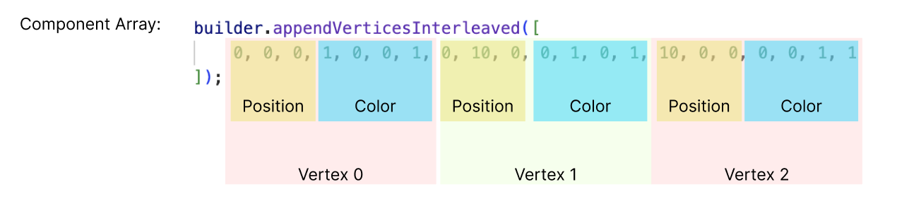
This function takes an array and automatically divides them based on how many attributes there are in MeshBuilder’s constructor.
For example, after we add color attributes, the function will read every 7 numbers as information stored under each vertex. To add three vertices to the MeshBuilder, we need 21 numbers in the function like below.
builder.appendVerticesInterleaved([
  0, 0, 0, 1, 0, 0, 1, 0, 10, 0, 0, 1, 0, 1, 10, 0, 0, 0, 0, 1, 1,
]);
The MeshBuilder will segment this array like below:
If we segment the array like the function will do, it looks like this below:
builder.appendVerticesInterleaved([
  // Position             Color                   Index
  0,
  0,
  0,
  1,
  0,
  0,
  1, // 0
  0,
  10,
  0,
  0,
  1,
  0,
  1, // 1
  10,
  0,
  0,
  0,
  0,
  1,
  1, // 2
]);
In this way, each vertex is assigned a different color based on the RGBA value. We can attach an unlit material to the mesh and connect the surface color node to the base color in the graph editor. We also need to enable two-sided in the material so that the triangle can be seen from both side:
We will get this triangle with this assigned color:
Function: setVertexInterleaved()
We can also dynamically change modify the mesh in run time by applying this function in an update event like this:
script.createEvent('UpdateEvent').bind(function (eventData) {
  builder.setVertexInterleaved(2, [
    10 * Math.sin(getTime()),
    0,
    10 * Math.cos(getTime()),
    0,
    0,
    1,
    1,
  ]);
  builder.updateMesh();
});
Remember to use updateMesh() every time you make any change to our MeshBuilder objects.
With this code, the third vertex will rotate around the center, so that we can see the triangle is rotating around the z-axis.