VFX
The VFX Template showcases different ways to use VFX Graph.
The Template comes with reusable VFX graphs that you can use in your own project, as well as complex examples that demonstrate how you can take advantage of VFX Editor to create stunning visuals.
These examples are structured from the simple to complex VFX so you can look at each example and compare with other examples to easily learn how the VFX Graph works and how easy it is to create a visual effect using the graph. Feel free to skip through the different section based on your interest!
If it’s the first time that you are using a VFX graph or node based particle system, we recommend first to look at the VFX Editor Overview.
Guide
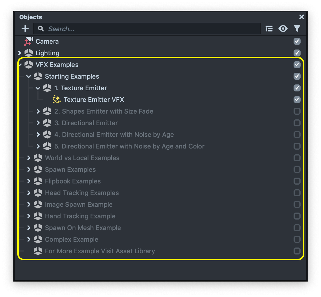
The template comes with several examples. These examples can be found in the Objects Panel under their names. Feel free to try them by enabling the example scene object.
The VFX Editor
Each example contains an object which contains a VFX component with the related VFX asset. Same as the Material Editor or Visual Scripting, to see or modify the vfx in each example, take a look at the corresponding VFX asset in the Resources panel. Then, double click on it to open it up in the VFX Editor panel.
or you can select the scene object that contains the VFX Component, then right click in the input field and click on the select option. This will select the VFX Asset in the Resources panel. Then, double click on it to open it up in the VFX Editor panel.
This guide will explore some of the examples found in this template.
Starting Examples
This is a step by step example, demonstrating how to create a simple fire using VFX Editor.
In the guide below we walk through each example on how to achieve a simple fire vfx.
Texture Emitter
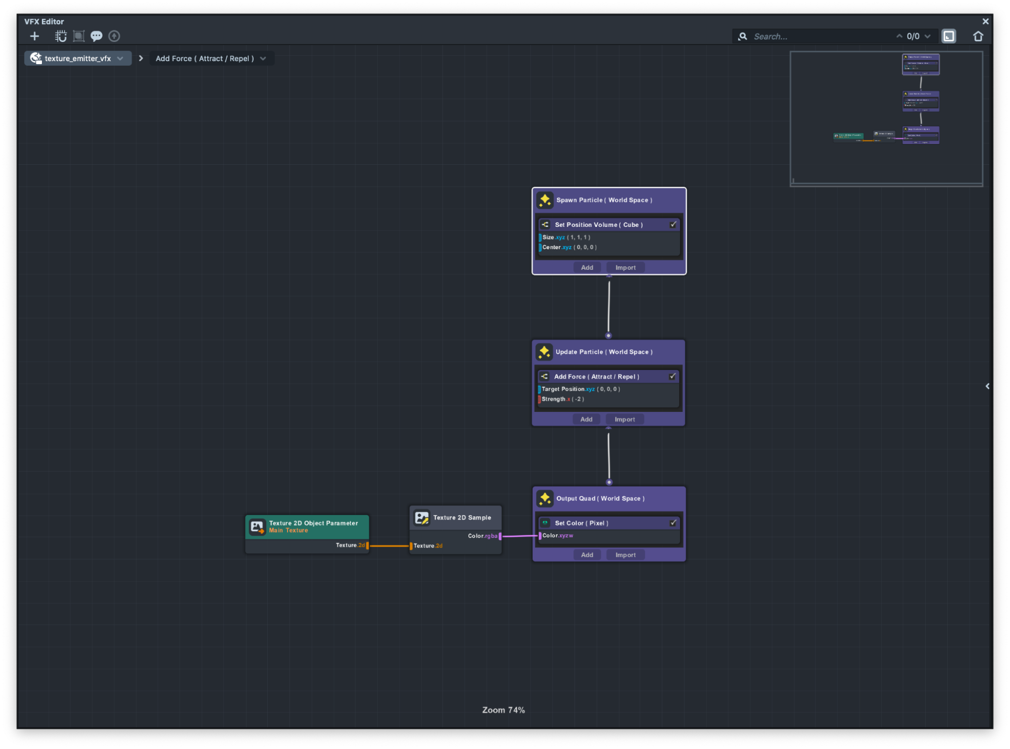
The Texture Emitter examples show how you can spawn a texture using VFX.
If you take a closer look at the Output container you can see that we have a Set Color (Pixel) sub-graph. Output is essentially a material applied to a two dimensional square mesh, also referred to as a quad and Set Color sub-graph lets you customize the color and transparency of each particle.
Texture 2D parameter node lets you choose a texture asset in the Inspector panel. Then, with the use of a Texture 2D sample you can simply convert the texture into an RGBA channel so you can then easily connect that to the Set Color node.
With this setup you can assign a texture to each particle. To learn more about texture optimization for VFX please visit the VFX Graph Optimization guide.
Shapes Emitter with Size Fade
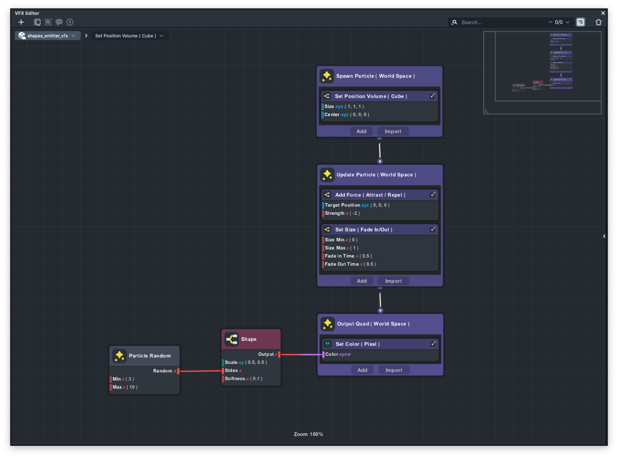
This VFX is almost identical to the Texture Emitter example but as you can see instead of rendering texture, we use the Shape sub-graph to create different shapes and apply it to each particle.
In the Shapes subgraph you can specify how many sides each shape has. For example if you want to have a triangle you can pass 3 which means three sides or if you want a square you can pass 4 to the sides.
If you take a closer look at the particles, you can see we have different shapes. This effect is achieved by using the Particle Random node. Particle Random nodes will return a random number between the min and max range for each particle. In this example you can see the min number is 3 and max number is 10 which means we’re getting 3 sided shapes which is triangle to 10 sides shapes which is almost a circle.
Directional Emitter
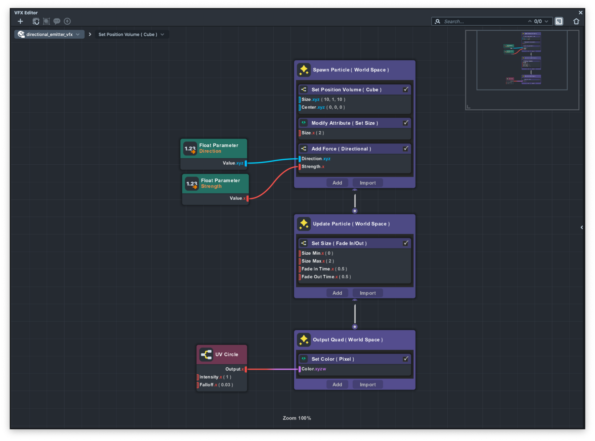
In this example you can see we added an Add Force (Directional) node in the spawn container to add a force to each particle in the direction that we want.
This Add Force subgraph can be either used in the spawn container or in the update container. The difference is that in the spawn container we just give it an initial force compared to the constant force.
Directional Emitter with Noise by Age
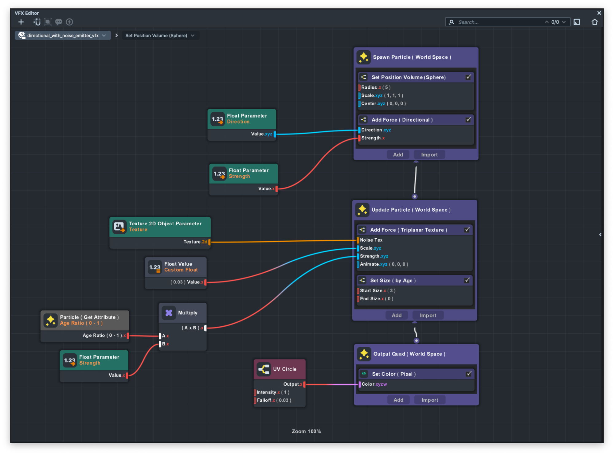
In this example as you can guess by the name, we added a Add Force(Triplanar Texture) subgraph to the Update container.
This subgraph uses a texture to apply a noise effect based on the texture to the particles.
If you take a close look, you can see that we use an Age Ratio 0 -1 node. This node will return the normalized particle age which is a number between 0 to 1. By that means when a particle gets born it will return 0 and as it goes and dies it will return 1.
We use this node to apply the noise as the particles grow older. So when it's born you see no noise and as it gets older you can see noise start adding to the particle.
Now you can see we’re getting closer to achieving the fire looks.
Directional Emitter with Noise by Age and Color
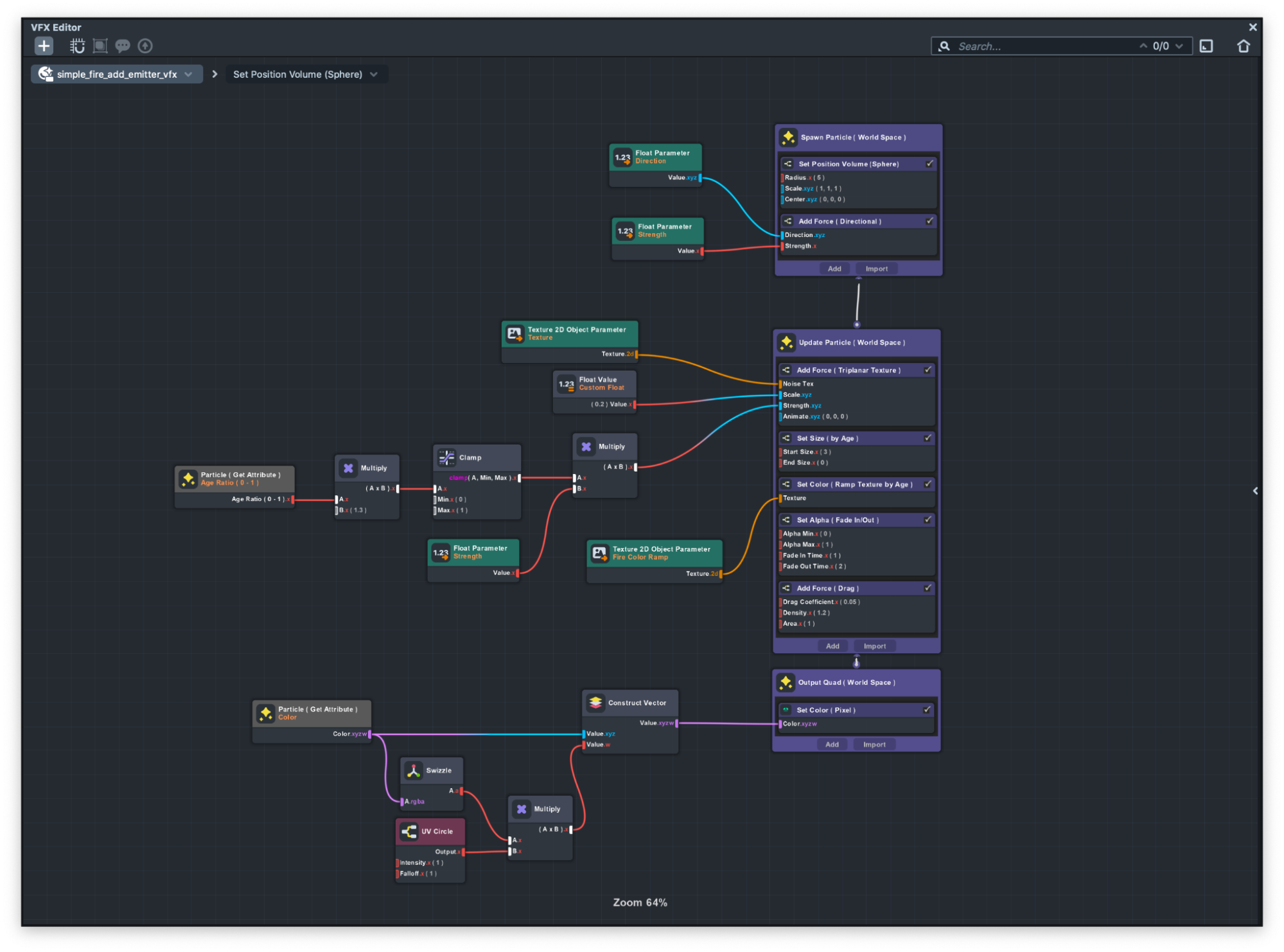
In this example you can see how by adding some colors as well as changing the blend mode we achieve the look of the fire.
If you take a closer look at the fire color you can see when it gets born its really bright yellow and as it grows the color changes to dark orange. You can specify the color through the particles age by using the Set Color ( Ramp Texture by Age ).
This subgraph gets a Texture and then based on the particle's age it applies a color to that.
Now let's see how we can change the blending mode of our particle. Output container is where you define how the particle is drawn to the screen. We can change the blending mode of the particle by selecting the output container and changing the blend mode in the properties section.
Keep in mind that each particle container has its own customizable value that you can change in the properties section of the VFX editor. We recommend that you take a look at each customizable value for each container.
World vs Local Examples
Particles can be simulated in World Space or Local Space.
Local Space simulates the effect locally to the Scene Object that holds the VFX Component But World Space simulates the effect independently of the Scene object that holds the VFX Component.
You can see the difference between Local Space vs World Space in the image below:
You can change the simulation space by selecting the either Spawn container or Update container and setting the space to either Local or World space.
Spawn Examples
This example shows the different types of spawning available in the VFX Editor. There are two presets available to choose from when spawning particles.
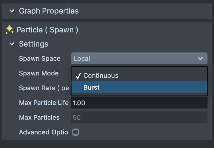
Continuous spawn mode will spawn particles continuously but Burst mode will spawn particles every couple of seconds that can be modified in the Spawn container.
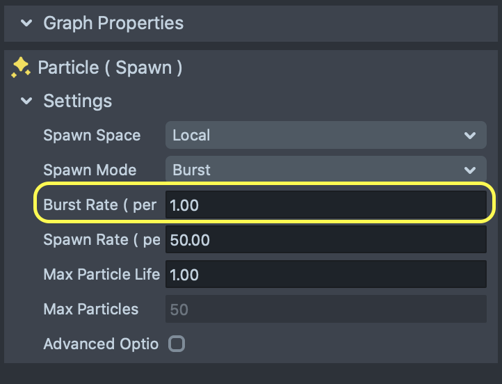
However you can have your own custom spawning. For example spawning the particles on tap or any other events only for a certain time. You can see the difference between them in the image below.
To change the Spawn mode, simply select the Spawn container and then in the Graph Properties section, change the Spawn mode to your choosing.
Interactive Spawn Example
Interactive spawn example showcase a way to create a custom particle spawning.
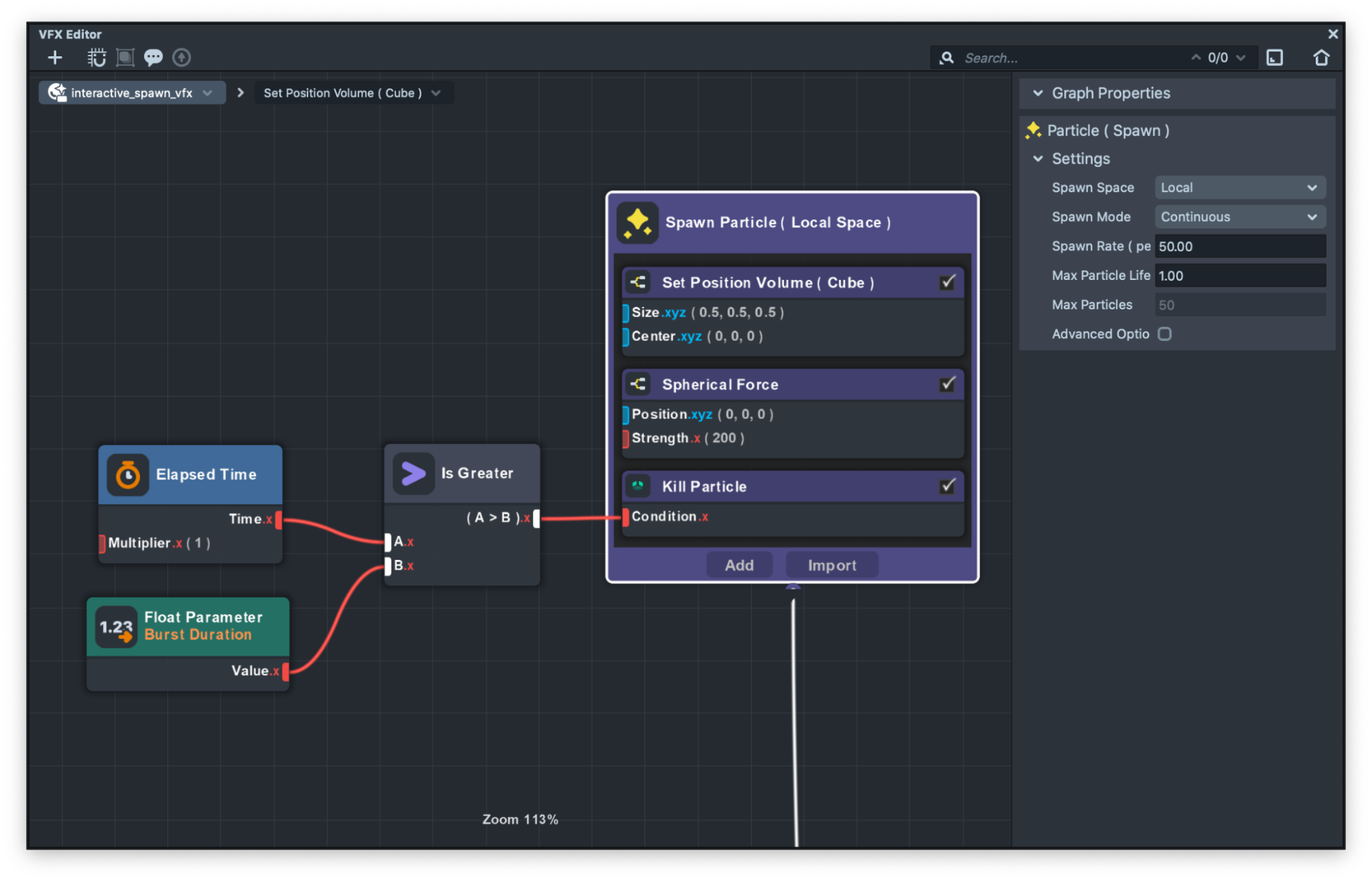
If we take a closer look at the graph we can see that we’re using the Kill Particle node in the Spawn container. This node has an input which if we pass 1 to this node it will kill the particles that makes that particle not visible or if we pass 0 it will not kill the particle.
This is very useful if you want to not show the particles at some points.
In this example we take advantage of this node to make an interactive spawning based on the logic that we specify. This logic gets controlled by JavaScript. Let’s take a look at that!
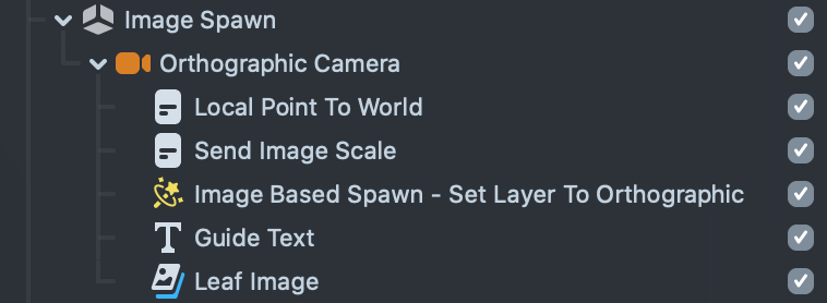
In the Objects panel, expand the Interactive Example - TAP object to see its children.
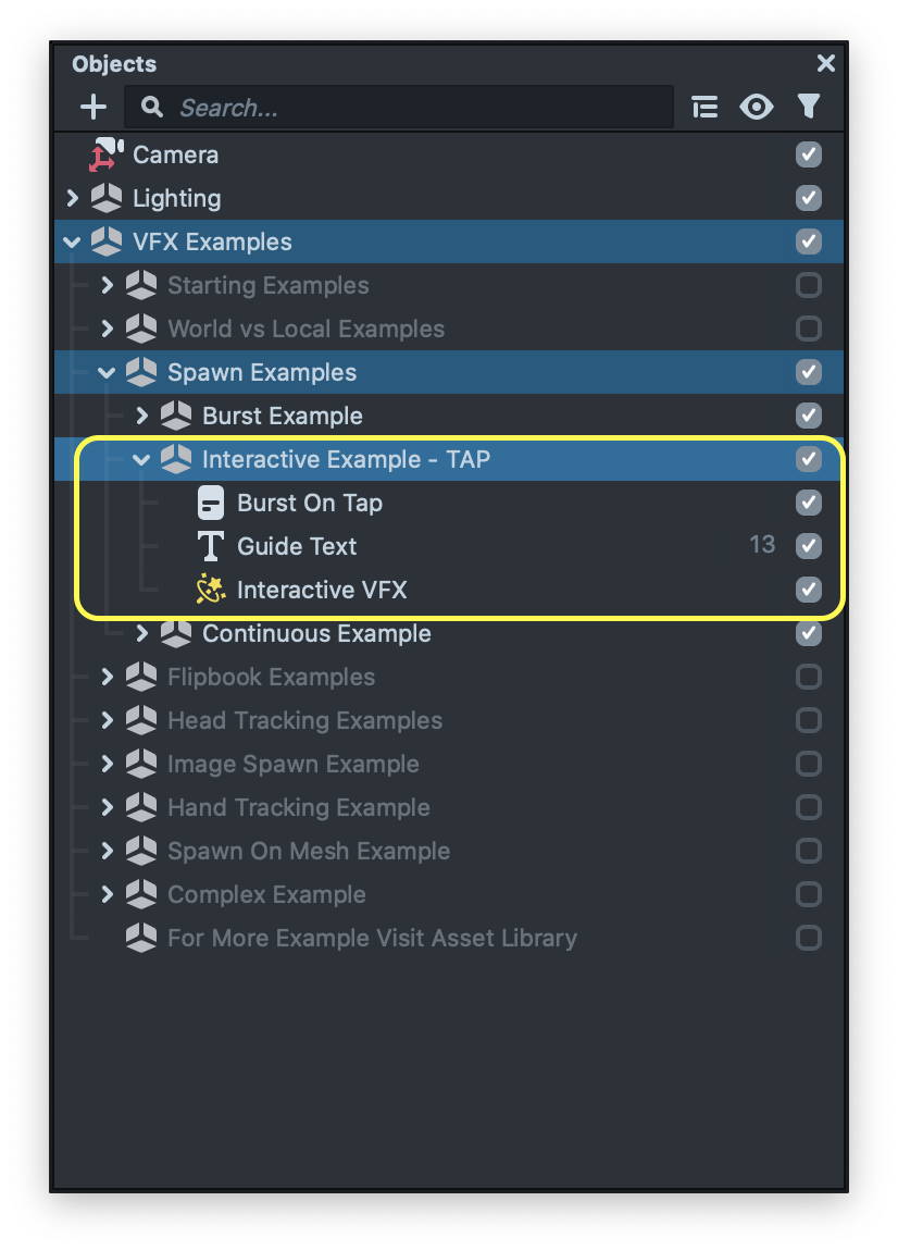
Now you can see there is an object called Burst On Tap which has a script attached to it. Then, open the script and let’s see how you can pass data to the VFX asset using JavaScript.
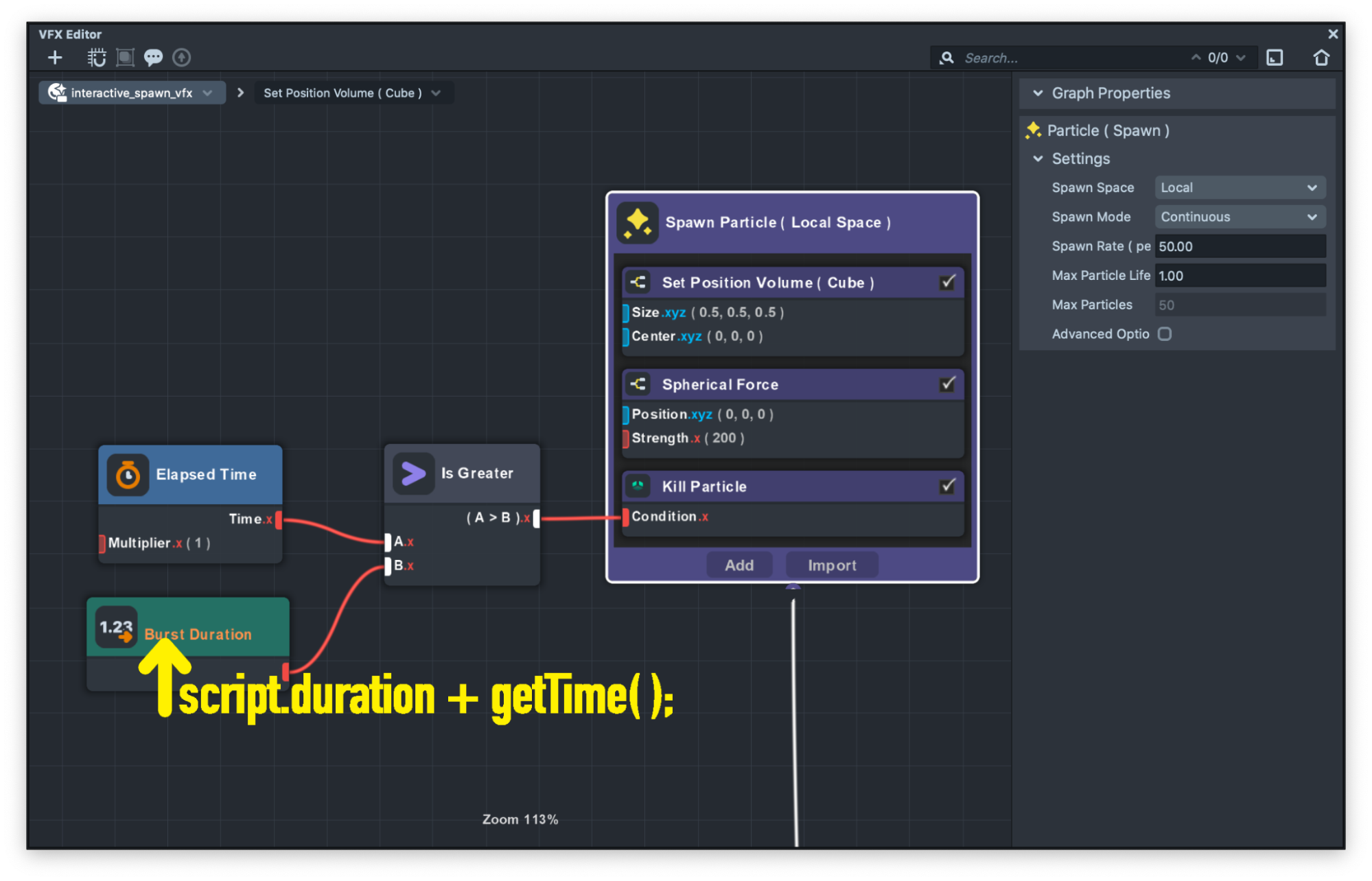
script.vfx.asset.properties['burstDuration'] = script.duration + getTime();
You can see we are passing the current time with addition of our spawn duration to the burstDuration input in the VFX graph.
You can use the script component event to choose which event can trigger the code and makes the VFX to spawn the particles.
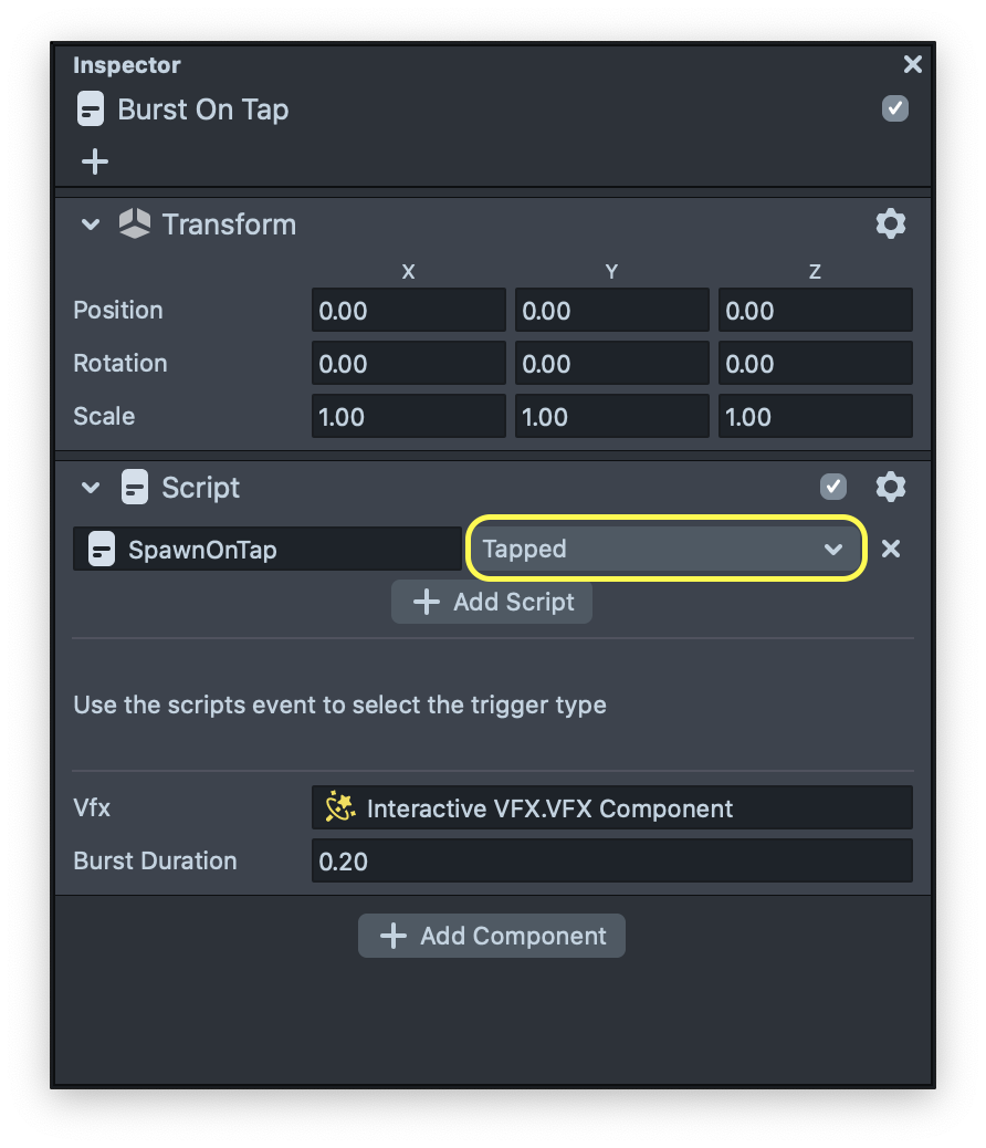
For this example it is set to trigger on tap but feel free to change it and make the spawn happening on other events.
At this point we covered all the basic examples of the template. Now let’s see how we can use what we learned to create cool and stunning visual effects!
Flipbook Examples
Flipbook examples demonstrate how you can assign animated images to each particle.
Simple Flipbook
This example is very similar to the texture spawn example. But in this case we use a special node called Flipbook Samples. This node samples colors from frames on an animated flipbook sheet and returns the RGBA value of it.
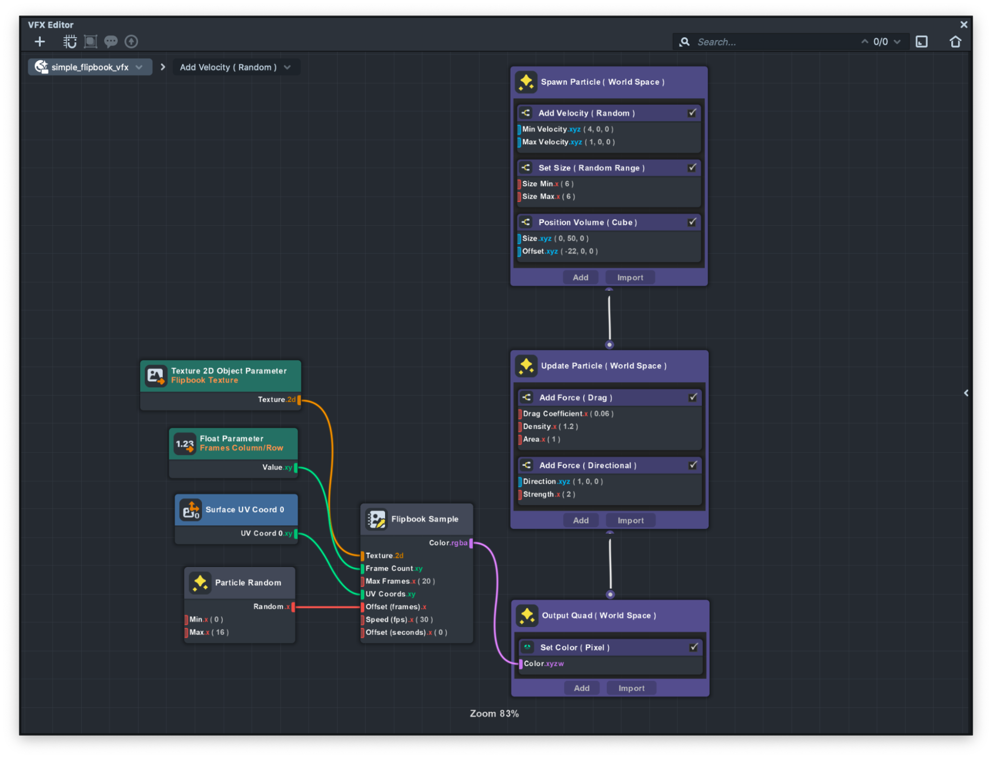
Take a look at the Flipbook Sample node to learn more,
Dynamic Flipbook
The Dynamic Flip Book VFX uses the same technique to show animated images on each particle. But there is an addition to it which when each particle reaches a certain position, it will dynamically change the animated texture to another texture.
In the guide below we will learn how to use Collision ( Bouncy Floor ) sub-graph as well as changing the texture based on the collision.
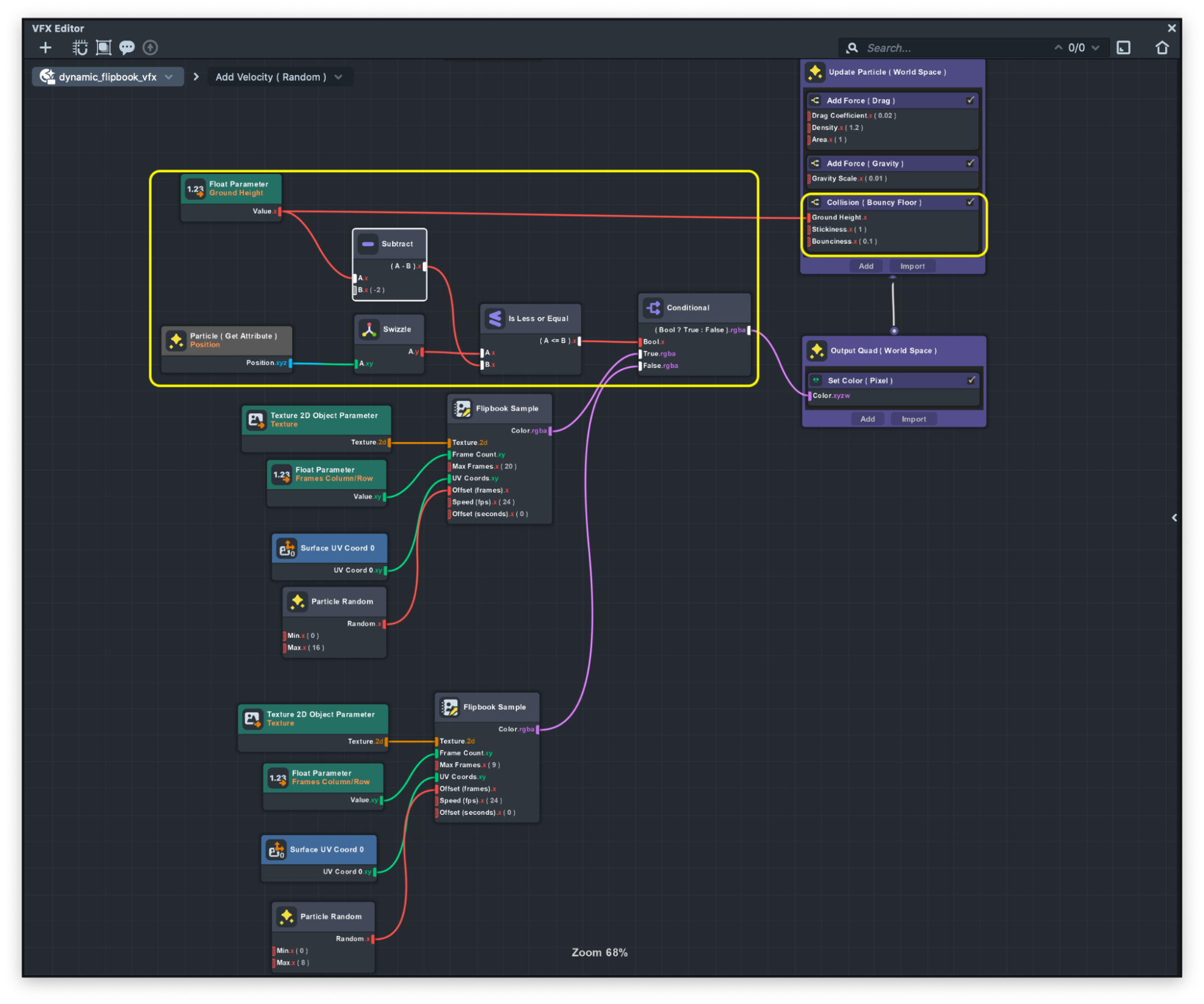
If we take a closer look at the dynamic_flipbook_vfx graph. We can see that we are specifying the ground height using the Ground Height parameter. This value can be customized in the Inspector panel to set where the position that if any particles reach that point the texture will change. You can see the logic in the image below
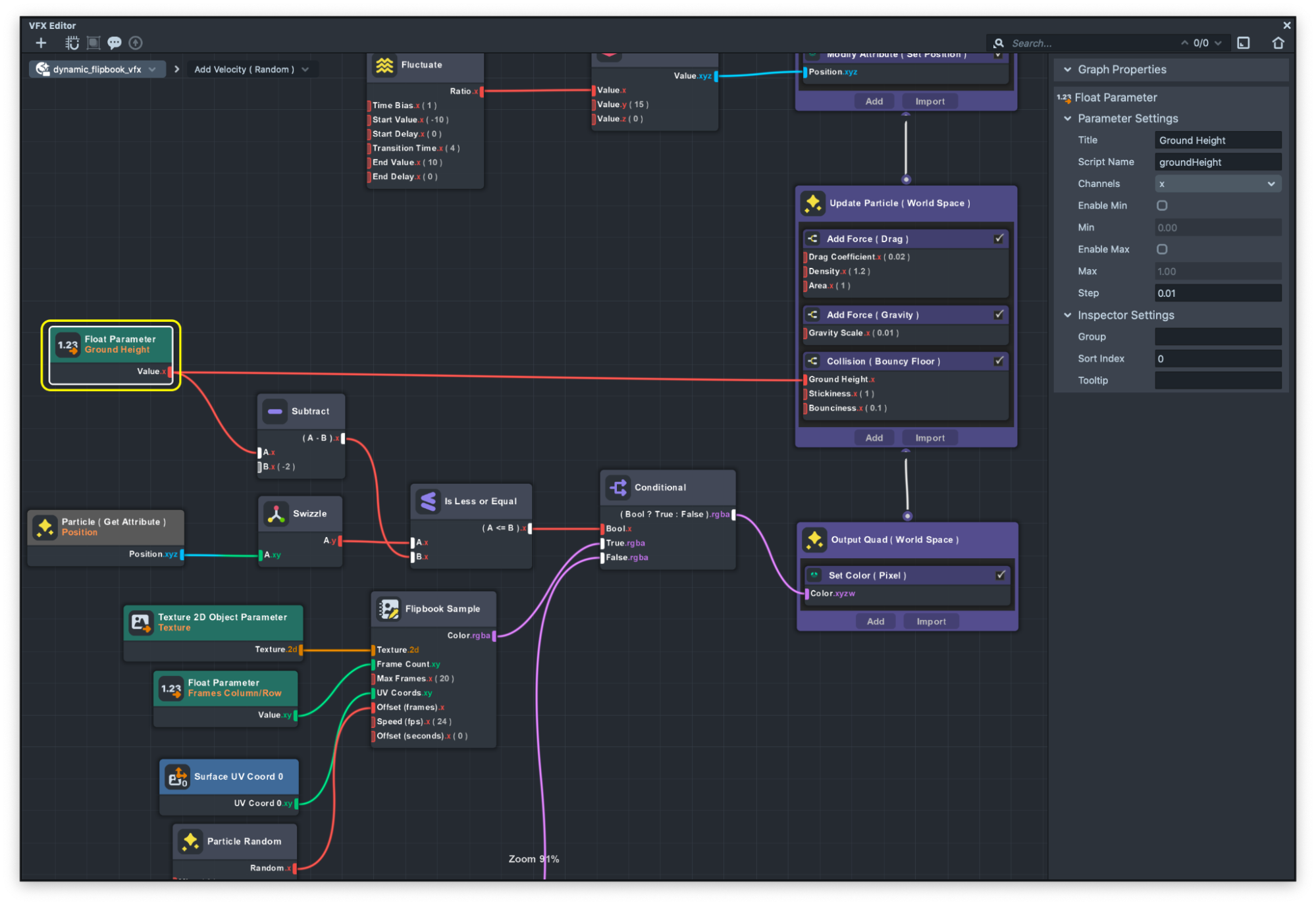
We also use this parameter to specify the ground position on the Collision ( Bouncy Floor) sub graph. This subgraph can be added only to Update container containers which by setting the ground position, you can have a collision for each particle.
This node is very helpful for creating effects like rain and more.
Head Tracking Examples
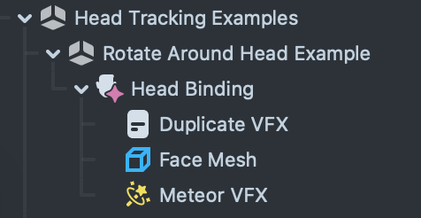
In this example we will see how we use head binding to spawn VFX that is attached to a face.
Rotate Around Head
Rotate around the head example takes advantage of simulation space as well as head binding to attach VFX to a head. Also we use JavaScript code to duplicate one vfx and place it around the head. We will start by explaining the VFX and then we will talk about how to duplicate the VFX using JavaScript.
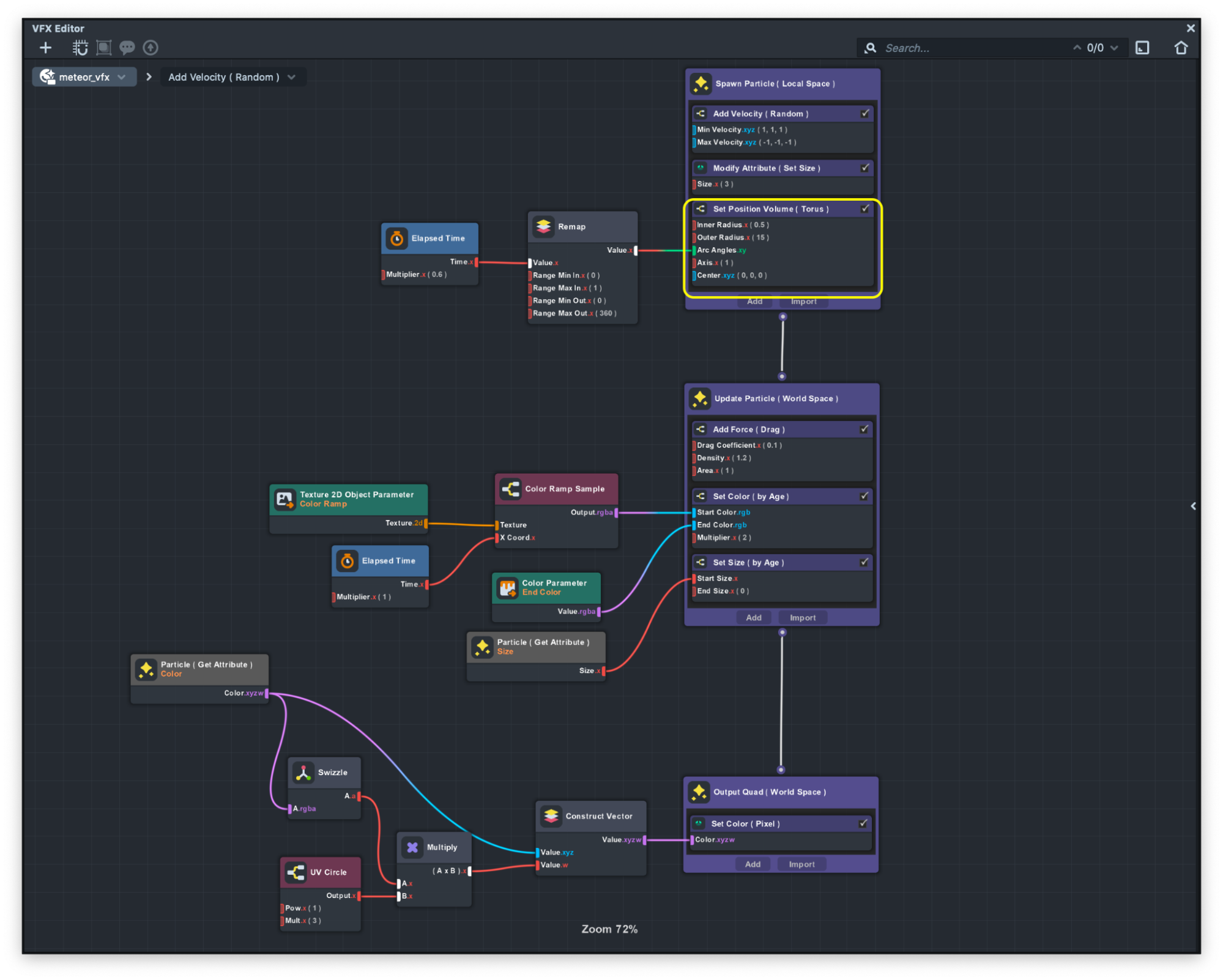
If we take a close look at the graph, we can see that there is a new sub-graph in the spawn container which is called Set Position Volume ( Torus ), As you can guess from the name, this sub-graph will spawn the particles in a torus shape.
The Set Position Volume ( Torus ) subgraph comes with lots of customizable values that you can modify to looks of the shape of the torus.
As you can see in the image below we use the time and remap the value of the time from 0 to 1 into 0 to 360 and pass it to the subgraph to make the particles move in the torus.
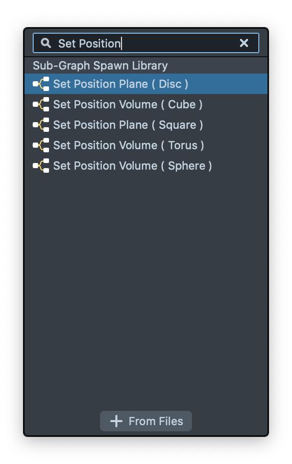
Same as the Set Position Volume ( Torus ), there’s a similar subgraph that helps you to spawn the particles in different shapes. We recommend checking the other subgraph as well!
This example uses a script called DuplicateVFXExample to show how you can easily duplicate the VFX asset and place it in the scene. Let’s open the script and see the script.
var newObj = global.scene.createSceneObject('');
var vfxComp = newObj.createComponent('Component.VFXComponent');
var newVfxAsset = script.vfx.asset.clone();
vfxComp.asset = newVfxAsset;
In this example you can see in the first line we create a new scene object and then assign a VFX component in the newly created scene object. Then you can see in the third line we take an advantage of JavaScript to access the asset of the VFX that we selected and use a clone() function to duplicate the asset. Finally in the last line we assign the cloned object to the component that we just created.
Now that we have a duplicated VFX we can easily place that anywhere in the scene. To learn more about scripting in Lens Studio please visit the API page.
Image Spawn Example
In this set of examples we learn how to spawn particles based on a texture. This texture can be segmentation textures or any other images.
Image Spawn
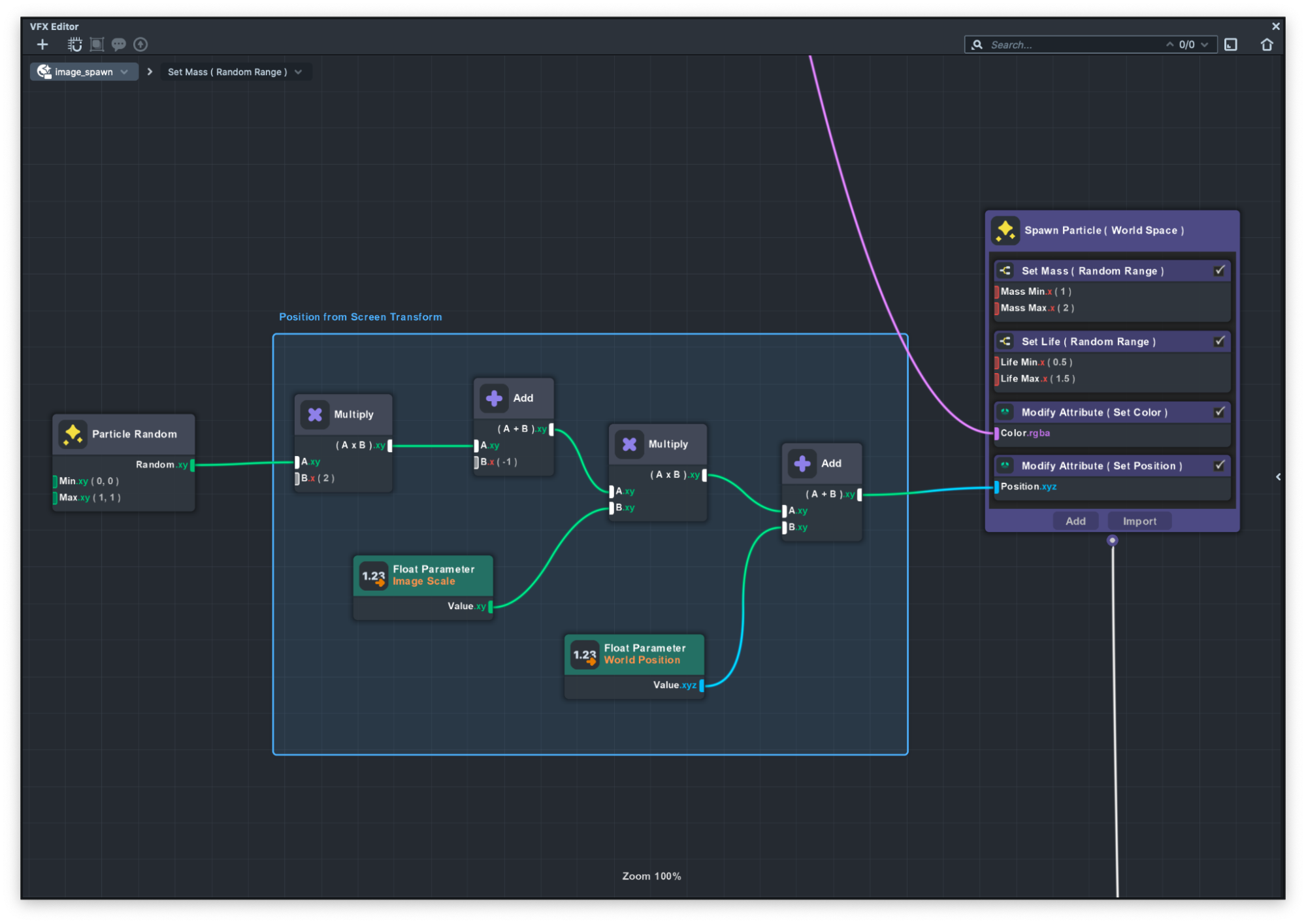
Image Spawn example, shows an easy solution for emitting from Screen Transform.
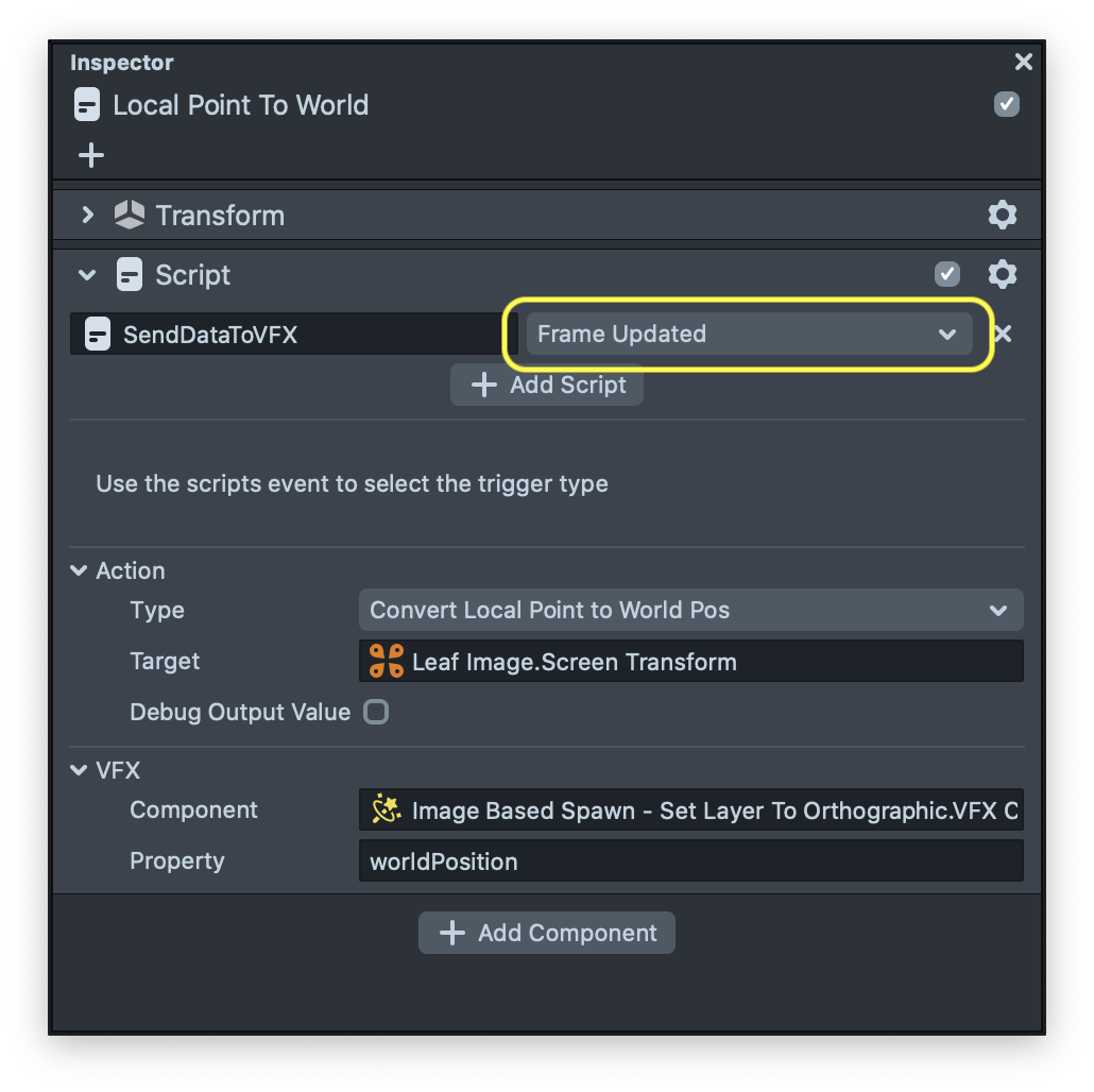
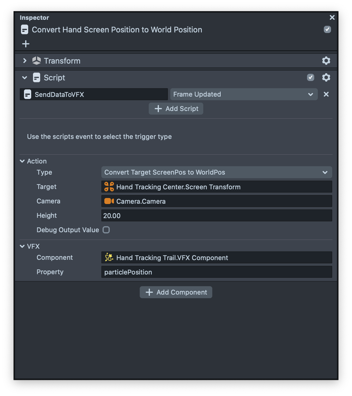
All the particles follow the position and colors of the image. In this template we provide a helper script called SendDataToVFX that helps you to easily send data from an object to your selected VFX without writing any custom script. With SendDataToVFX script, interactions are completely configured in the Inspector panel.
The SendDataToVFX helper script's interface is broken out into three sections:
-
Event: Defines when data should be send to VFX asset
-
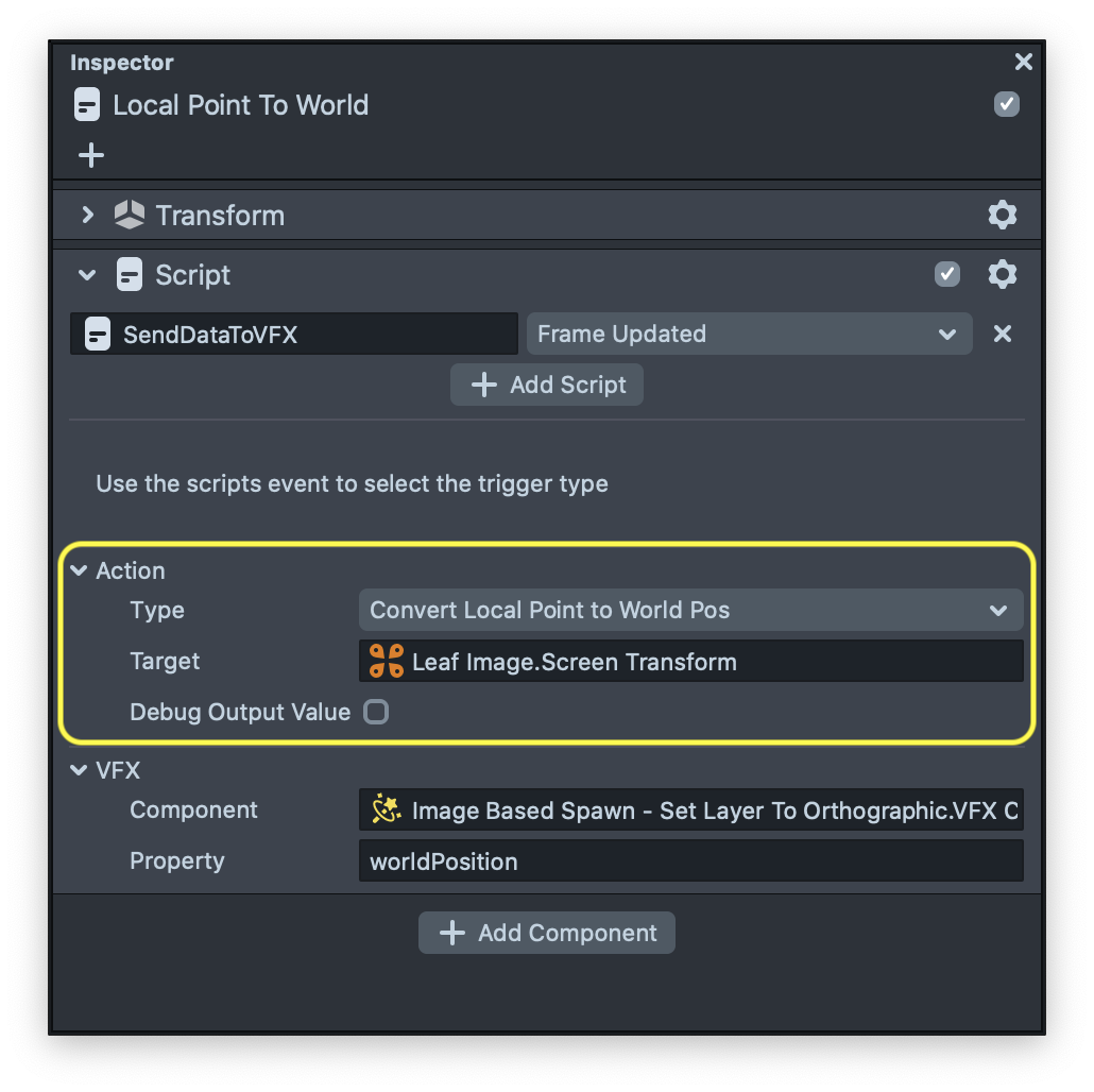
Action: Defines what kind of data should be send to VFX asset
-
VFX: Define VFX component as well as parameter which receive data
In this example we use this script two times to send two different values to the VFX asset.
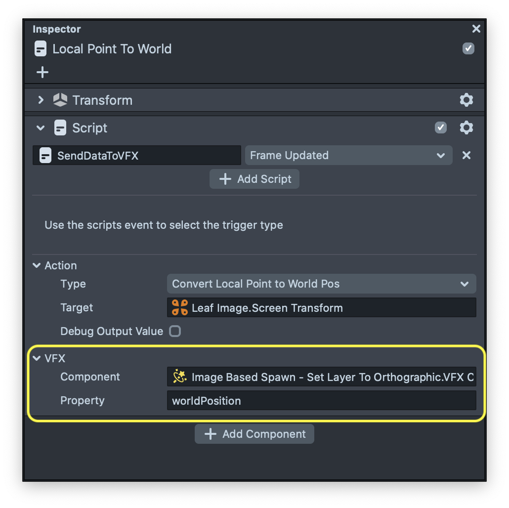
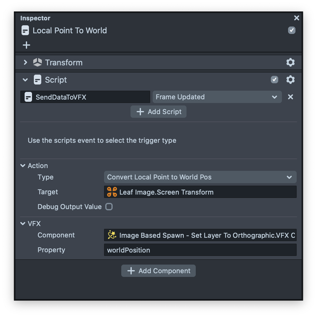
In the first SendDataToVFX script we need to convert the screen point to world position, since the image that we spawn from is in the screen space (Contains screen transform).
You can see in the VFX section we specify the VFX component and in the property section we put the script name of the VFX’s parameter that we want to modify using the script.
Based on what we explain above in this script we’re getting the screen transform of the image and sending the vec3 world position of the image into the worldPosition of the VFX’s component.
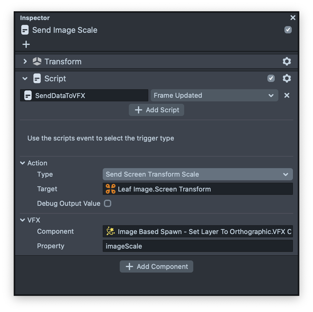
And then in the second SendDataToVFX script we send the screen transform scale to the imageScale property of the VFX.
Now that if we look at the graph you can see that we have two green nodes. These green nodes are parameters nodes that contain some value and these values can be updated using the inspector panel or using scripting. In our examples we are getting values using the SendDataToVFX script. With these two values we can easily set the position of the particles using the Modify Attribute (Set Position) node. To learn more about the Modify Attribute please visit the guide.
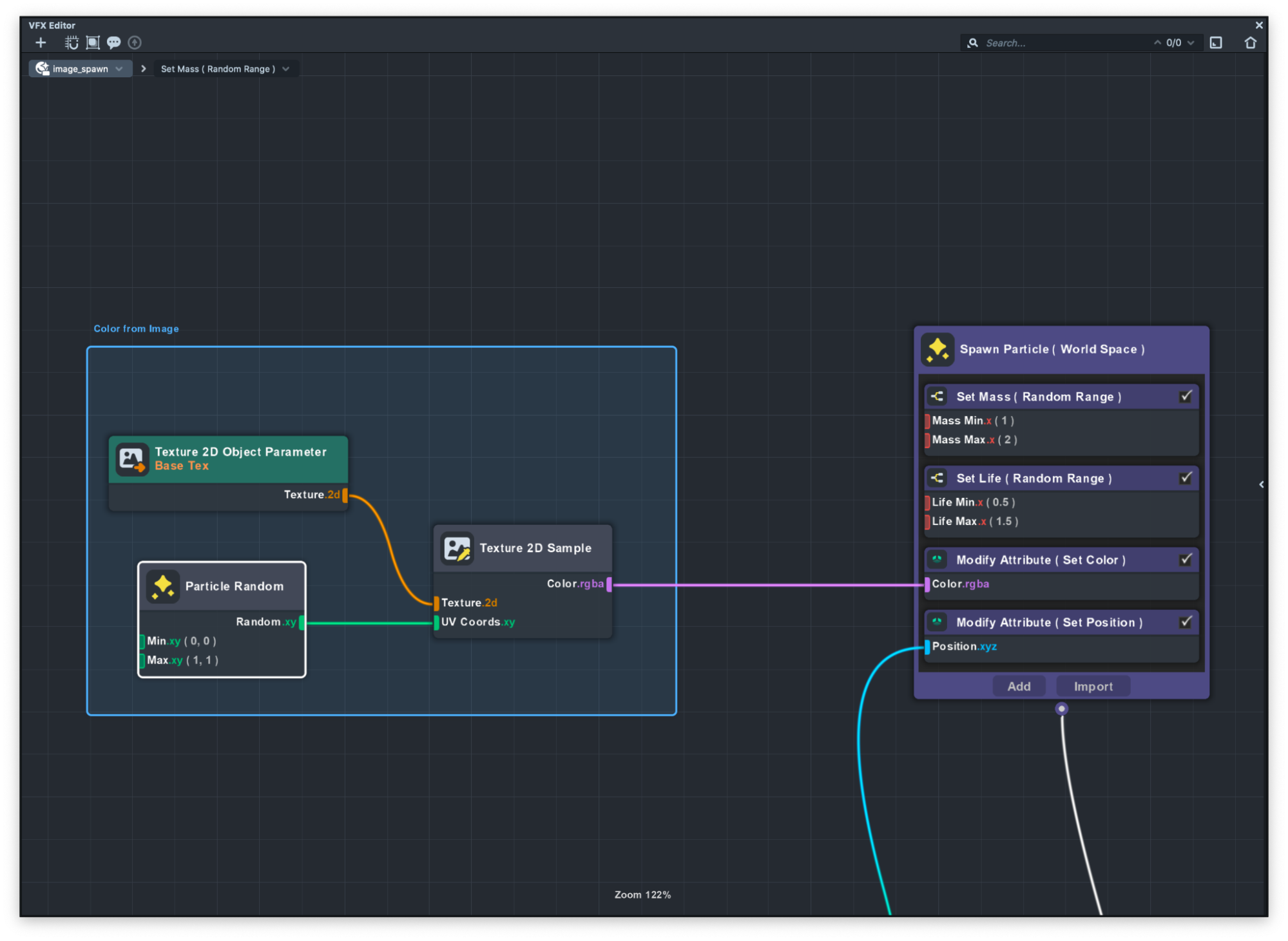
To make each particle color be the same as the image we need to sample a color from the image. In the graph you can see there is a Texture 2D Object Parameter that we sample colors from based on each random particle and then pass the RGBA data to Modify Attribute (Set Color) node.
Segmentation Spawn
Segmentation spawn is using the same technique to spawn particles based on a texture.
In this example our texture is a render target that we’re capturing using the Segmentation Camera. Click here to learn more about Render Targets and Cameras.
In the image below you can see the output of the segmentation texture. You can see that we are replacing the background with black texture using Segmentation.
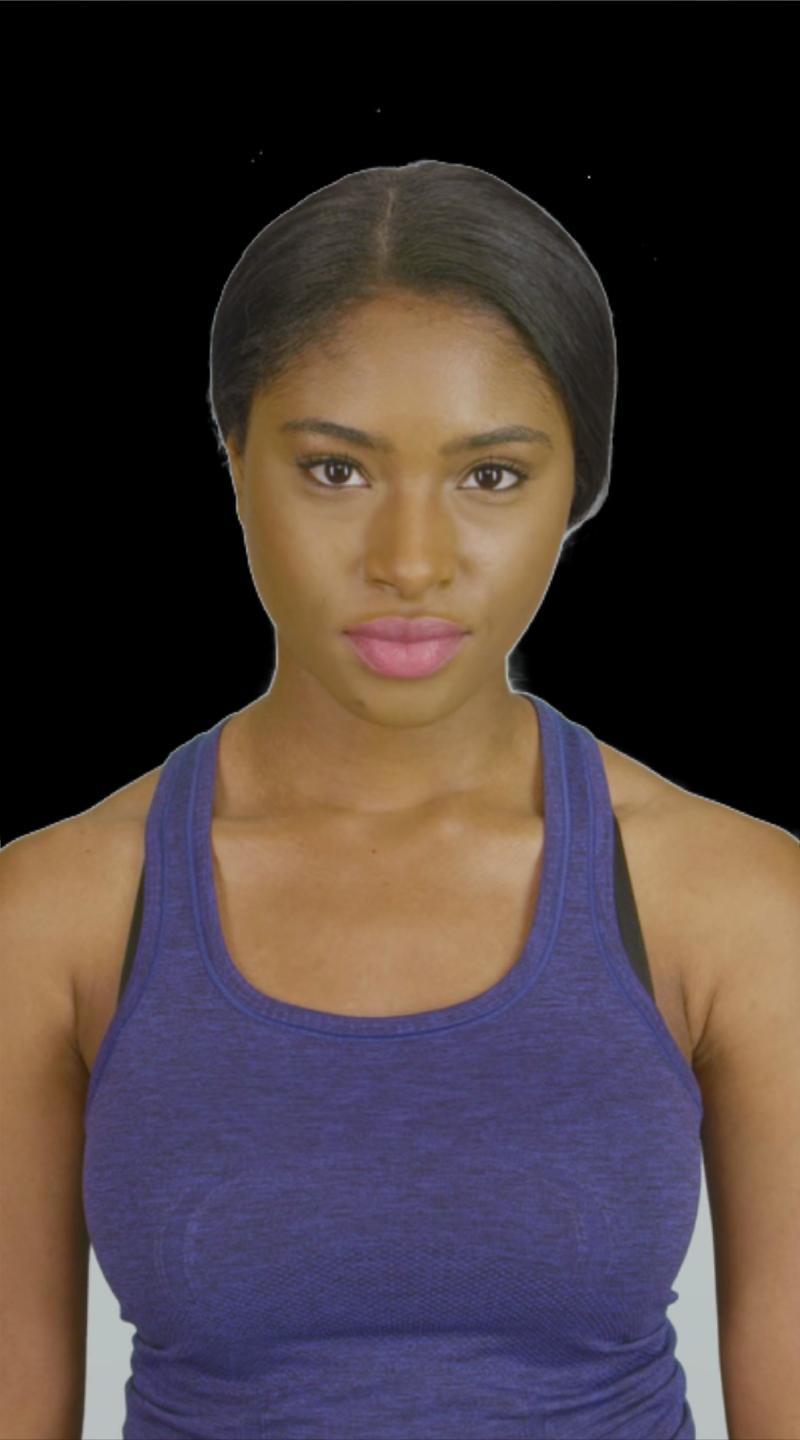
Now that we have this image we can spawn particles from this image, but in this example we only spawn a particle if that part of the image is not black, In other word if the particle that we spawn is black we just kill that particle.
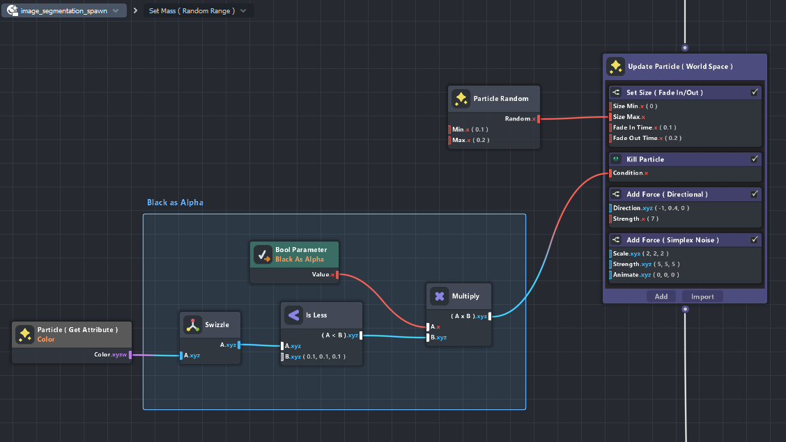
You can see in the graph we are getting the particle color using the Get Attribute node and just compare the RGB to see if it's a black color or not. If it was black we just kill the particle using the Kill Particle node. With this technique you can easily spawn particles on a Segmentation texture.
Hand Tracking Example
Hand Tracking example uses the hand tracking data to spawn particles on at the hand position. This example is the same as the Image Spawn example uses a SendDataToVFX script to convert the Hand position from screen space to world position and send that data to VFX.
Since we want to spawn the particles only when the hand tracking is happening, we use a behavior script to tell the VFX if the hand tracking is detected or its not detected.
In the example below you can see how easy it is to send data to VFX Assets using a behavior script.
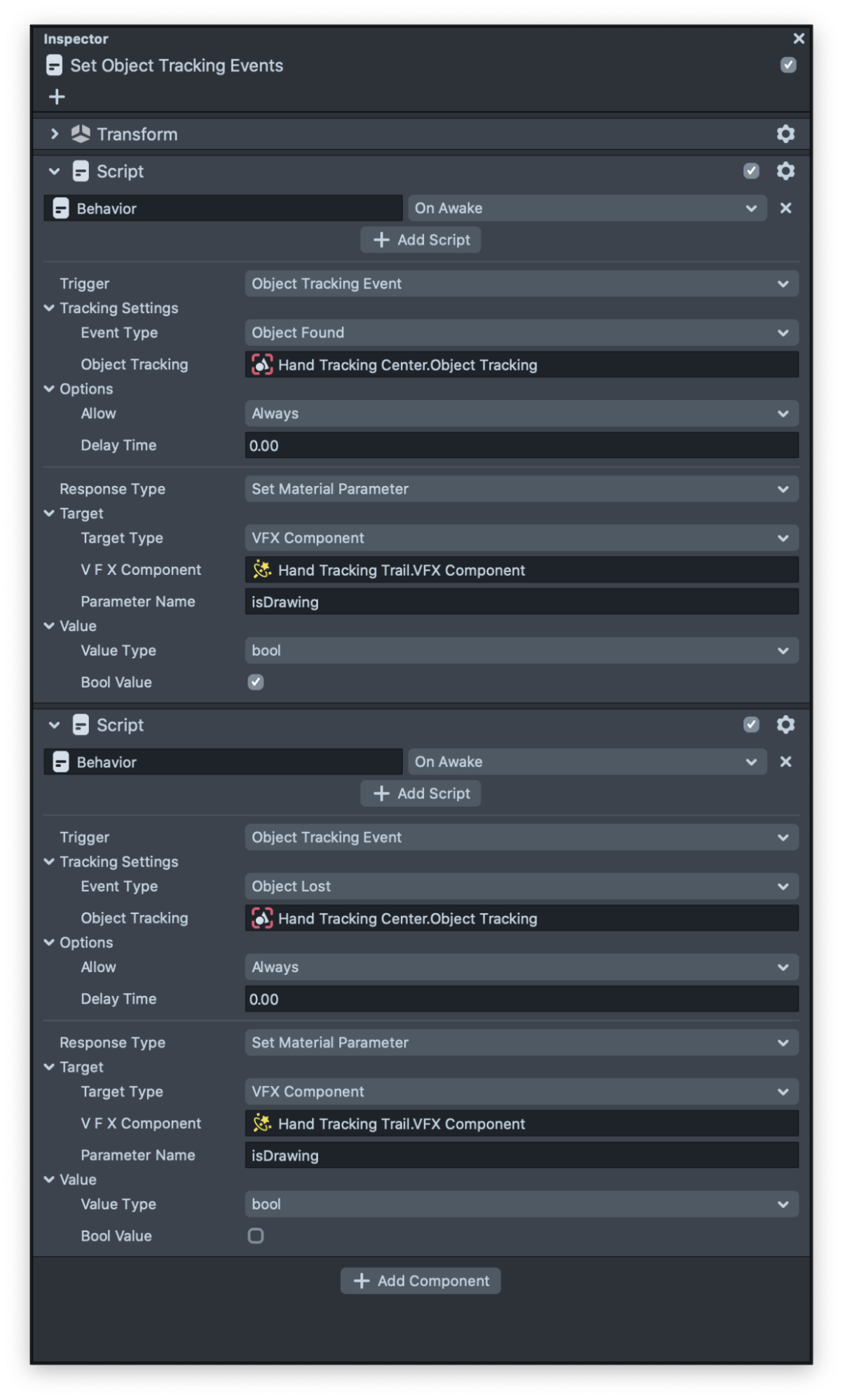
All the helper scripts provided by Lens Studio such as Tween and Behavior are now supporting VFX. Make sure to try them.
Spawn On Mesh Example
VFX Editor brings customizable particle systems to Lens Studio, making it very powerful to create complex, interactive effects. One common application of particle systems is to enable interaction with existing scene geometry. Spawn On Mesh examples demonstrate one technique for spawning particles on deforming mesh positions while reading the mesh’s normal and velocity data.
This example provided a helper script called EncodeMeshPositions which is responsible for reading the mesh data and passing it as a texture to the VFX.
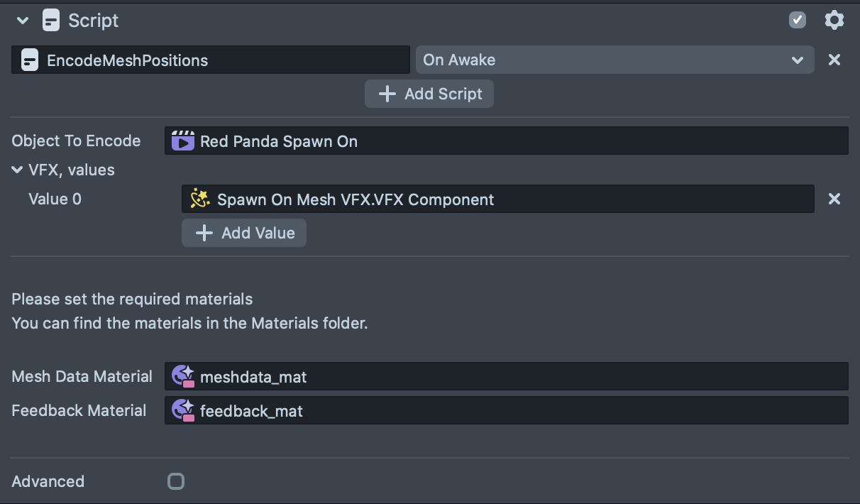
Both Spawn On Red Panda and Spawn On Face Mesh examples use the same workflow, in the guide below you can see exactly what EncodeMeshPositions does during each event.
On Start:- Set up two MRT (multiple render target) passes: our main one--the MRT Encode Data Camera--with 4 render targets to store mesh data, and another one--the MRT Feedback Camera--with 2 render targets to act as a feedback buffer (aka “blit”) for positions
- Duplicate the geometry we want to encode, assign it the
Graph Encode Mesh Datamaterial, and render it under the main MRT Encode Data Camera layer
On Update:- Encode mesh positions, normals, and velocity into the first MRT group
- Store the position data from the current frame into the second MRT group
- Send all 4 render targets from the first MRT group to the VFX Asset to process and use in the effect
VFX Editor stores particle data into texture buffers, so the most straightforward way of getting particles to spawn on mesh positions is to store the mesh positions into textures as well. Once mesh data in textures, it’s easy to get particles to sample the textures and use the data for all sorts of interesting effects.
The Encode Mesh Data Material
The first thing to look at in this material is its vertex shader. Since we are assigning this material to geometry we want to encode, we need to transform the geometry’s vertices to be in a 2D space that captures as much of its surface as possible. The easiest way of doing that is to just use it’s UV positions as the vertex position, which is what you see here:
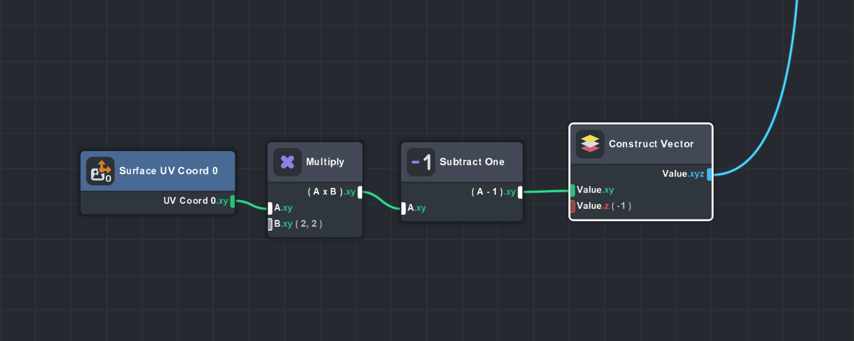
This takes the first UV coordinate attribute, which goes from 0.0 to 1.0, and puts it into a range of -1.0 to 1.0 so it’s centered around the origin. A small Z offset puts it in front of the orthographic camera, which is set up in the Mesh Encode Positions Script.
Using this technique, it’s important that your geometry has good UVs- minimize or eliminate overlaps in UVs, and ensure good coverage across the UV space.
Now that our pixel shader is writing colors in 2d texture space, we can think about what data we want to put there. Geometry can be anywhere in the world, so in this setup we are going to store the mesh positions in world space. Since Lens Studio does not yet support floating point textures, we will encode positions as 16 bit values using Material Editor’s Pack node. One 16 bit value requires two color channels in an RGBA texture, which means we can’t store the full XYZ position into a single texture, just XY. So we put Z into the second render target of our main MRT Encode Data Camera.
Normals are more straightforward: 8 bit precision is enough for our needs, so we simply need to remap the normals, which go from -1.0 to 1.0, into a 0.0 to 1.0 range.
Velocity is calculated by taking the difference between the current position and the previous position. We stored the previous position into the second MRT group in step 2b of our workflow, so it’s simply a matter of decoding these positions and subtracting them from the current position. Since the velocity vector can be a negative number, we remap from some starting range--in this case -10.0to 10.0--into 0.0 to 1.0 range, similar to how we handle the normals.
The full layout of the MRT Encode Data Camera across 4 render targets is:
- XY positions, 16 bit (X = RG, Y = BA)
- Z position, 16 bit (Z = RG)
- Normals, 8 bit (XYZ = RGB)
- Velocity, 8 bit (XYZ = RGB)
The VFX Asset
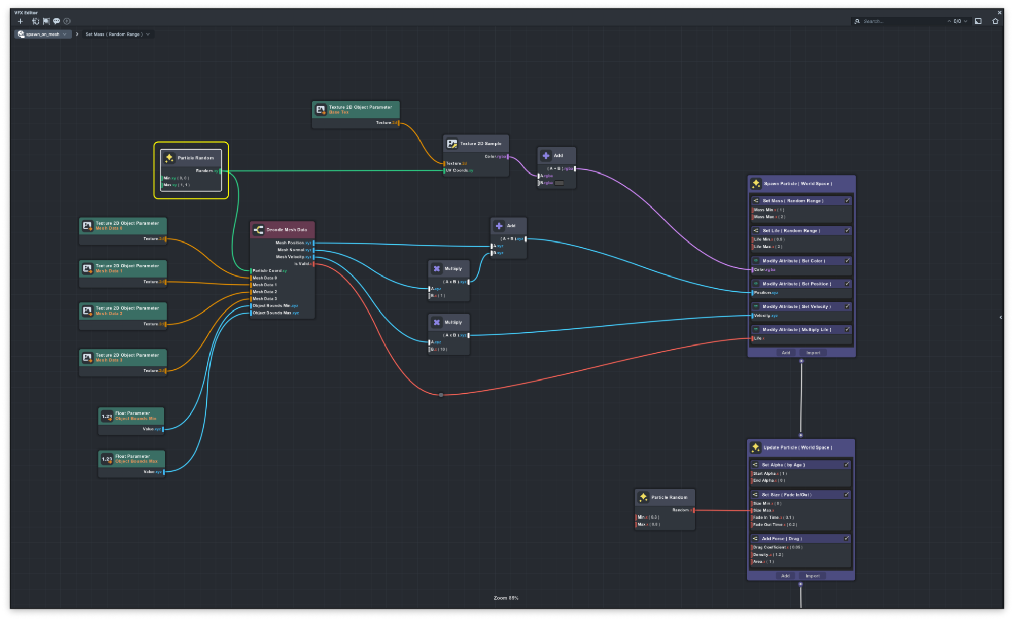
Finally, we have to read all this data in a VFX asset to do something cool with it. This project provides a sub-graph in the VFX Read Mesh Data asset called Decode Mesh Data, which returns the decoded values of all 4 render targets. If you look inside, you see that we are using the Unpack node to decode the 16 bit position data from the first two render targets. We also map the normal back from0.0 to 1.0into their original -1.0 to 1.0 range. We do the same for velocity.
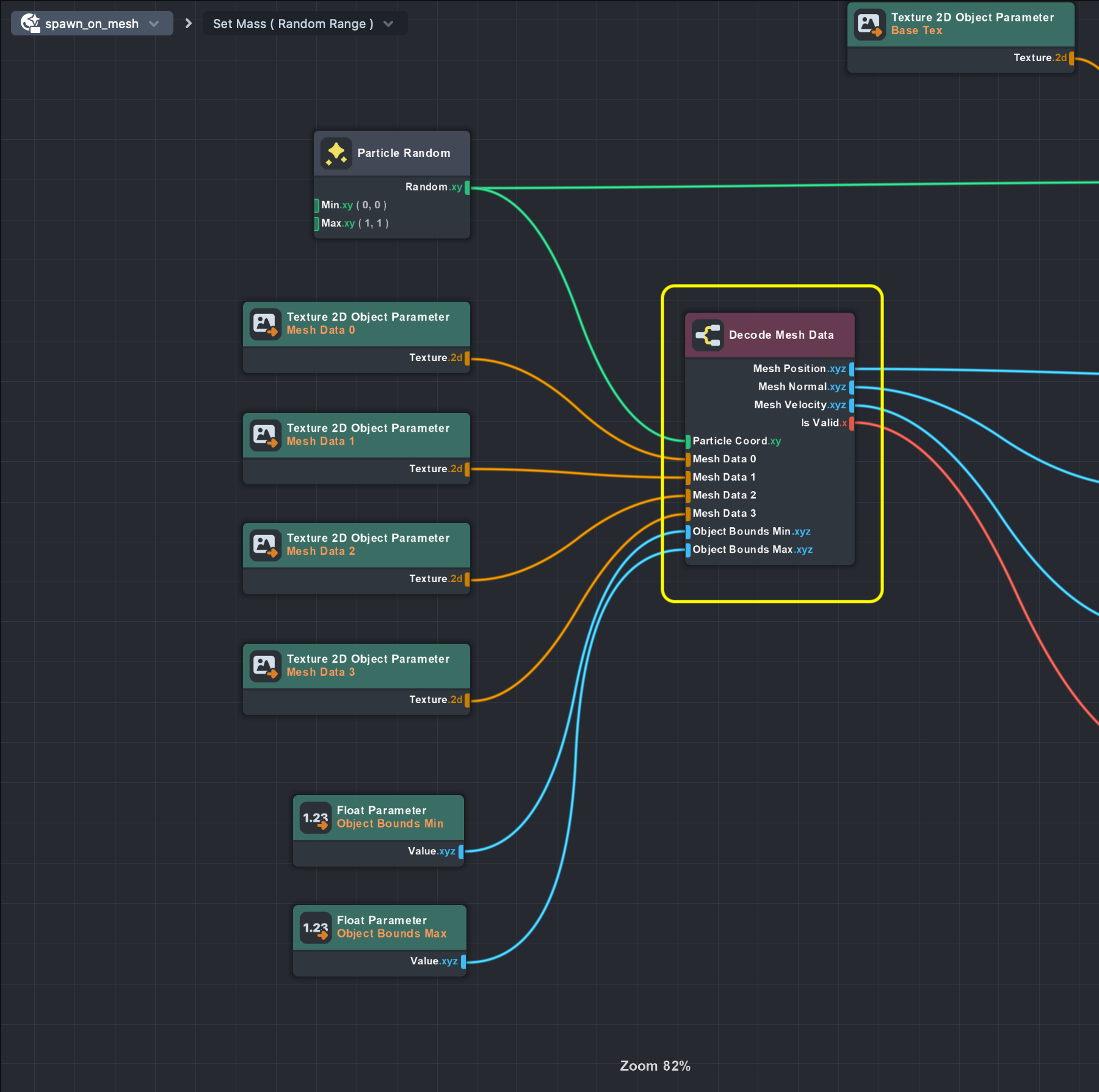
Something you might have noticed both here and in the Encode Mesh Data material are two uniforms: ObjectBoundsMin and ObjectBoundsMax . While 16 bit values give us a huge jump in accuracy over 8 bit, it is not completely error-free for all numbers. The Pack and Unpack nodes require a hint of the minimum and maximum range of values it expects before encoding them. Since the encoding and decoding step should get the same minimum and maximum values, we send these numbers as uniforms to both assets from the Encode Mesh Positions Script. The Mesh Encoder Scene Object exposes these min/max values for you to adjust as needed.
Ok, so how do we sample the textures from VFX Editor? Individual particles don’t have a standard UV coordinate, so instead we can just use a two-channel Particle Random node to give us a unique number that we can use as a texture coordinate. When only used in the Spawn container, setting Particle Random’s seed to Unique will ensure good coverage over time when reading textures (see Particle Random documentation for more information).
Textures can be sampled with different filtering modes, which allows for blending between pixels. In this case, we don’t want blending as it can lead to bad data when reading the texture. Make sure the filtering mode is set to Nearest for all mesh data textures.
This sub-graph also does one extra trick to help us with spawning particles: it offers an IsValid output that tells the system if the sampled position is useful or not. Because it’s pretty common that geometry UV’s do not cover the entire UV space, there may be a lot of empty, unused pixels in the mesh data textures. The sub-graph will check if there’s any data in the sampled position to make a decision if it’s a valid pixel or not. If not, it’s best that we don’t spawn a particle here.
Once you have the positions, normals, and velocity, you are free to play around and make cool things happen. This example project shows setting the particle position on spawn, offsetting it a little along the mesh normal so it’s not right on top of the mesh geometry, and sending the mesh velocity to the particle’s Velocity attribute. The example also will kill the particle on spawn if the IsValid value is False.
To recap, this project shows an example of encoding mesh data into texture maps and reading it in VFX Editor to drive particle animations. This technique adds a lot of power and interactive potential to VFX Editor. Since positions are in world space, they work well on basically any mesh that has UV’s, including skinned geometry and Face Mesh. Being in texture space allows us to leverage Material Editor and VFX Editor together to create performant, high quality effects.
There’s room to extend this project to add more functionality. If you take a close look at the layout of our 4 render targets, you’ll notice a few unused channels: the Blue and Alpha channels of the 2nd render target, and the Alpha channels of the 3rd and 4th render targets.
You are free to add any data you want to these channels that could make your particle simulation more interesting. For example, you could add a mask in one of the channels to control where particles spawn, or how big or fast they should be. Since VFX Editor and Material Editor are completely open to editing, you can tweak these assets to suit your specific effect.
Complex Example
The complex example is made out of all we learned from all the examples and combine them all to create stunning visual effects. We already explain all the techniques in other examples. Feel free to look at the VFX asset and see how this example is set up.
For More Example Visit Asset Library
Please visit Asset Library for much more examples such as how you can control the time of the VFX asset to pause or fast forward the VFX.
Previewing Your Lens
You’re now ready to preview your Lens! To preview your Lens in Snapchat, follow the Pairing to Snapchat guide.
Related Guides
Please refer to the guides below for additional information: